Now more and more portable electronic products, home audio-visual systems and car audio systems use class D amplifiers. Class D power amplifiers have the characteristics of power saving, high output power, good sound quality and stable signal. Lishui qingmuhua research report points out that driven by the demand for energy saving, light and short audio players, the global market sales of class D amplifiers will exceed US $750 million in 2012. Even under the impact of the financial crisis, the demand for class D audio amplifiers has not decreased at all.
The interference of EMI noise to surrounding equipment and circuits is completely unpredictable. There are a large number of RF systems in the mobile phone, such as call, radio and other functions. Generally speaking, relevant regulations will be required for EMI. Printed circuit board, clock circuit, oscillator, digital circuit and processor will become the internal EMI source of the circuit. Some electromechanical devices that perform switching operations on current produce EMI during critical operations. These EMI signals do not necessarily have a negative impact on other electronic devices. The spectrum composition and intensity of EMI signal determine whether it will have an unexpected impact on sensitive circuits.
For class D power amplifiers, there are two main ways to reduce EMI:
1. For the sampling frequency of power amplifier, spread spectrum technology is adopted to make the EMI interference spectrum caused by sampling frequency more average, so as to reduce EMI.
2. Control the opening and closing time of the output tube, and then control the EMI interference at the edge. It is generally believed that the second point is the main factor affecting the EMI of class D power amplifier.
The spectrum component of PWM signal is simplified to its frequency and rise time. The clock or system frequency establishes the time reference of the circuit, but its edge rate forms interference harmonics. The energy of EMI mainly depends on the change time and amplitude. Electromagnetic interference (EMI) can be transmitted in two ways: conduction and radiation. That is, electromagnetic interference is divided into conductive electromagnetic interference and radiated electromagnetic interference. When the frequency of electromagnetic interference wave is less than 30MHz, electromagnetic interference mainly produces conductive noise in electronic equipment in the form of conduction; When the frequency of electromagnetic interference wave is higher than 30MHz, electromagnetic interference mainly produces radiated noise in electronic equipment in the form of radiation. At present, the general EMI standards are FCC and CISPR, which mainly focus on the interference in the 30MHz frequency band.
The relationship between the maximum frequency of EMI generation and the edge change time is shown in the following formula. For example, when the edge change time is 10ns, Fmax = 31.8mhz is calculated, that is, the system will be affected by the frequency within 31.8mhz.
Class D power amplifier also has disadvantages. When the output signal of class D power amplifier is a pulse width modulation switching signal with high current and high speed, when the switching signal is transmitted to the horn through the horn line, it will indirectly cause electromagnetic wave radiation and produce electromagnetic interference (EMI). This EMI interference contains a wide spectrum. Different frequency bands interfere with different receivers, and even interfere with non receiver electronic products.
The following are common solutions to EMI interference
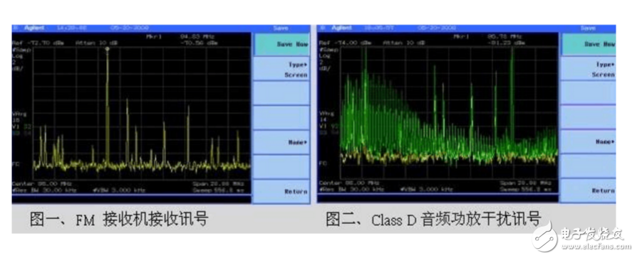
Figure 1 shows the received signal at the antenna end of a general FM receiver. When the class D power amplifier operates, if the radiated harmonic signal is not effectively processed, the result will be as shown in Figure 2. The harmonic signal covers the original FM signal, which reduces the FM receiving quality or even cannot be received
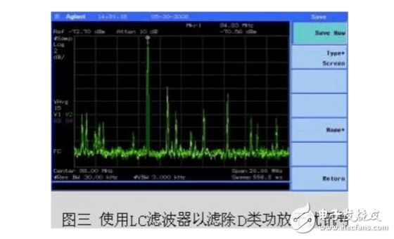
EMI interference can be solved from two aspects: radiation and conduction. The selection of PCB layout and LC filter to block radiation interference is an effective treatment direction. According to the frequency band radiated by class D power amplifier, adjusting the combination of output LC filter can effectively improve the FM reception quality. As shown in Figure 3: the interference phenomenon in the original figure 2 can eliminate the interference problem of class D power amplifier after being processed by appropriate LC filter.
In addition to the isolation of the power source on the PCB / layout, some are also the transmission source on the PCB.
It is also possible to reduce the intensity of the interference signal. It is mainly to change the interference frequency. Shortening the horn line of class D power amplifier can reduce the transmission efficiency of antenna (horn line) and reduce the intensity of interference radiation wave.
The method to reduce the intensity of interference radiation wave is to use LC filter to filter the switching signal of class D power amplifier, take out its audio signal, and then transmit it to the horn through the horn line. In this way, the transmission signal of the horn line is an audio signal, and the high-frequency switching signal has been greatly attenuated. Since the length of the horn line of class D power amplifier is relatively short in the application of portable electronic products, magnetic beads can be used to filter some special high-order harmonics without using LC filter.
Another way to reduce the interference signal is to use the spread frequency technique. The way of frequency spreading is to change the high-frequency carrier frequency of class D power amplifier with time, so that the interference signal is distributed in several frequency regions rather than all concentrated in one frequency region. If the high-frequency carrier frequency rotates at 10 frequencies on average, the EMI can be reduced by 10dB in theory.
Using frequency hopping method can also effectively avoid interference. If the receiver is powered by class D power amplifier when receiving a certain frequency
If disturbed by the high-frequency switching signal of class D power amplifier, the high-frequency switching frequency of class D power amplifier can be jumped to another frequency. Since the audio content of class D power amplifier is independent of its carrier or switching frequency, this method does not affect the content of audio signal. As long as the switching frequency is not within the band-pass filter range of the receiver, the receiver can effectively suppress the interference signal.
The solution to FM interference in the market adopts metal shell shielding, so as to attenuate the interference energy of harmonic radiation and make FM reception normal. However, when FM receiver is combined with class D power amplifier, this shielding method is not applicable, and EMI prevention of class D power amplifier must be started.
|
Disclaimer: This article is transferred from other platforms and does not represent the views and positions of this site. If there is infringement or objection, please contact us to delete. thank you!
中恒科技ChipHomeTek
|

 Service mailbox
 13823783658
 ChatNow