The basic circuit of low dropout linear regulator (LDO) is shown in Figure 1-1. This circuit is composed of series regulator VT, sampling resistors R1 and R2, and comparison amplifier a.
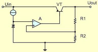
Figure 1-1 basic circuit of low dropout linear regulator
The sampling voltage is applied to the in-phase input terminal of comparator a and compared with the reference voltage UreF applied to the inverted input terminal. After the difference between the two is amplified by amplifier A, the voltage drop of the series regulator is controlled to stabilize the output voltage. When the output voltage uout decreases, the difference between the reference voltage and the sampling voltage increases, the driving current output by the comparison amplifier increases, and the voltage drop of the series regulator decreases, thus increasing the output voltage. On the contrary, if the output voltage uout exceeds the required set value, the front drive current output by the comparison amplifier decreases, thereby reducing the output voltage.
During the power supply process, the output voltage correction is carried out continuously, and the adjustment time is only limited by the reaction speed of the comparison amplifier and the output transistor circuit. It should be noted that the actual linear regulator should also have many other functions, such as load short-circuit protection, overvoltage shutdown, overheat shutdown, reverse connection protection, etc., and the series regulator can also use MOSFET.
|
Disclaimer: This article is transferred from other platforms and does not represent the views and positions of this site. If there is infringement or objection, please contact us to delete. thank you!
中恒科技ChipHomeTek
|

 Service mailbox
 13823783658
 ChatNow