Now let‘s analyze the specific working principle:
Assuming that the input voltage is UI, when UI rises for some reason, ud1 rises correspondingly. It can be seen from the characteristics of the voltage regulator that a small rise in ud1 will cause Id1 to increase sharply. In this way, the IR1 current flowing through R1 will also increase, and the voltage ur1 at both ends of R1 will rise. R1 will share a large part of the value of UI rise, and ud1 can remain stable, so as to achieve the purpose of maintaining the stability of voltage UR2 on the load. This process can be represented by the following change diagram:
UI↑→UD1↑→ID1↑→IR1↑→UR1↑→UD1↓
On the contrary, if the UI drops, it can be represented by the following change diagram:
UI↓→UD1↓→ID1↓→IR1↓→UR1↓→UD1↑
It can be seen from the previous analysis that in the silicon regulator circuit, D1 is responsible for controlling the total current of the circuit and R1 is responsible for controlling the output voltage of the circuit. The whole voltage stabilization process is completed by the joint action of D1 and R1.
2. Component selection
Now let‘s take a look at how to design a silicon stabilized voltage supply when the load voltage ur1 and load current IR1 are known.
(1) Primary selection of regulator D1
Generally, the regulator D1 can be preliminarily selected according to ud1=ur2 and Id1 ≈ (IR2) max. if the load is likely to be open circuit, then (Id1) max ≈ (2-3) (IR2) max should be selected, because all currents will flow through D1 when the load is on, so Id1 should be appropriately larger..
(2) Selected input voltage
Generally, ui= (2-3) UR2 can be selected
(3) Selected current limiting resistor R1
R1=(UI-UR2)/(ID1+IR2)
However, two limit cases need to be considered:
When UI is the largest and the load is open circuit (i.e. ir2=0), the current flowing through D1 is the largest. In order not to exceed the maximum allowable current (Id1) max of D1, a sufficient current resistance is required, otherwise D1 will be burnt out. Then R1 needs to meet:
When UI is minimum and the load current is maximum, the current flowing through D1 is minimum. In order to ensure that D1 can work in the breakdown area and play the role of voltage stabilization at this time, a certain current should flow through D1, generally 5ma-10ma. Then R1 needs to meet:
R1<((UI)min-UR2)/(ID1+(IR2)max)
R1>((UI)max-UR2)/ ID1)max
The value of current limiting resistor R1 should be selected within the range of the above two formulas.
(4) Check the stability of the circuit
The stability of the circuit needs to be determined according to the requirements of the actual circuit. If the stability is not enough, R1 and UI can be added appropriately, and the regulator with small dynamic resistance R can also be selected.
2、 Transistor parallel regulated power supply
1. Circuit principle analysis
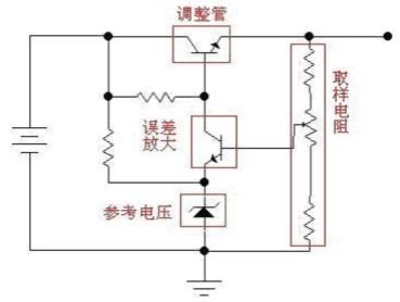
Figure 3-1-2 shows the transistor parallel regulated power supply. Where T1 is the regulator, D1 is the reference regulator, R1 is the current limiting resistance of D1, R2 is the current limiting resistance, and R3 is the load. The output voltage of this voltage stabilizing circuit is approximately equal to the voltage stabilizing value of the voltage stabilizing tube D1 (in fact, the T1 emission junction voltage should be added. Generally, the germanium tube is 0.3V and the silicon tube is 0.7V).
This is because when the power supply is working, the T1 emitter junction is on, the emitter voltage is consistent with the base voltage, and the base voltage is stabilized at a fixed value by D1. This circuit can be regarded as T1, amplifying the voltage stabilizing effect of D1 β Times, which is equivalent to connecting a voltage stabilizing value of D1, and the voltage stabilizing effect is β A voltage stabilizing tube with a voltage stabilizing effect of times D1.
The working principle of the circuit is:
UI↑→UD1↑→(UT1)EC↑→(IT1)EC↑→IR2↑→UR2↑→(UT1)EC↓
UI↓→UD1↓→(UT1)EC↓→(IT1)EC↓→IR2↓→UR2↓→(UT1)EC↑
2. Component selection
The steps of selecting components in this circuit are similar to the parallel voltage stabilizing circuit of silicon voltage stabilizer, mainly from the following aspects.
(1) Primary selection of adjusting tube T1 and stabilizing tube D1
When selecting the regulating tube T1, its rated current ICM should be greater than the output current IO to ensure that the regulating tube will not be damaged due to excessive current when the load is open circuit. In addition, in order to ensure that the adjusting tube has a good adjustment effect, it is also required that β High value and low leakage current.
When selecting regulator D1, it is mainly considered that the sum of its stable voltage and T1 emission junction voltage should be equal to the output voltage.
(2) Selected input voltage
In order to ensure the efficiency of the regulated power supply, the input voltage should not be too high, and should not exceed 2 UI.
(3) Selected current limiting resistor R2
For the parallel voltage stabilizing circuit, the current limiting resistance R2 is the key to the operation of the whole circuit. With large R2 selection, the voltage stabilization effect is good, but the power consumption is large (because the resistance power consumption p=i2r), and the input voltage is required to increase, so the efficiency of the power supply is relatively low. The specific calculation method can refer to the third step of component selection of parallel voltage stabilizing circuit of silicon voltage stabilizer.
(4) Check the stability of the circuit
The stability of the whole circuit needs to be determined according to the requirements of the actual circuit. If the stability is not enough, R1 and UI can be added appropriately, and you can also choose β Adjustment tube with large value and small leakage current.
3. Parallel regulated power supply using composite regulator
Figure 3-1-3 is a parallel regulated power supply using a composite regulator tube. The biggest difference from the circuit in figure 3-1-2 is to change the regulator tube to conform to the tube structure, so that a larger β Value, and can have a larger ICM. The method similar to that in figure 3-1-2 can be used for component selection. However, due to the large current of this circuit, it should be noted that the power of current limiting resistor R1 should be considered in addition to the resistance value. In order to avoid burning out the current limiting resistance when the load is open circuit.
4. Advantages and disadvantages of parallel regulated power supply
·Advantages of parallel regulated power supply:
·When the load changes, the voltage stabilization performance is better.
·It has good adaptability to instantaneous changes.
·With overload self-protection performance, the adjusting tube will not be damaged when the output is open circuit.
Disadvantages of parallel voltage stabilizing circuit:
·The output voltage regulation range is very small.
·It is not easy to achieve high stability.
·The efficiency is low, especially when the load is light, almost all the electric energy is consumed on the current limiting resistor and regulating tube.
In fact, these advantages of parallel regulated power supply can be realized by using some special circuits for series regulated power supply. However, these inherent shortcomings of parallel regulated power supply are difficult to improve, so now commonly used are series regulated power supply.
The above is some knowledge about DC regulated power supply introduced by Xiaobian. I believe that through Xiaobian‘s explanation, everyone knows about DC regulated power supply. With the development of science and technology, DC regulated power supply has been widely used in various fields of DC power supply, including national defense, scientific research, industrial and mining enterprises, laboratories and so on.

 Service mailbox
 13823783658
 ChatNow