The difference and relation between decoupling capacitance and bypass capacitance
In electronic circuits, decoupling capacitors and bypass capacitors both play the role of anti-interference. The names of capacitors vary with their positions.
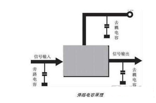
For the same circuit, the bypass capacitor takes the high-frequency noise in the input signal as the filtering object and the high-frequency clutter carried by the previous stage as the filtering object, while the decoupling capacitor takes the interference of the output signal as the filtering object.
Decoupling capacitor is often connected between power supply and ground, which has three functions: first, as the energy storage capacitor of this integrated circuit; The second is to filter out the high-frequency noise generated by the device and cut off its transmission path through the power supply circuit; The third is to prevent the noise carried by the power supply from interfering with the circuit.
The bypass capacitor takes the interference in the input signal as the filtering object, while the decoupling capacitor takes the interference of the output signal as the filtering object to prevent the interference signal from returning to the power supply. This should be their essential difference. Decoupling capacitor is equivalent to battery, which avoids voltage drop due to sudden change of current, and is equivalent to filtering ripple. The specific capacitance value can be calculated according to the current, the expected ripple and the action time. Decoupling capacitors are generally large, which is basically ineffective for higher frequency noise. The bypass capacitor is designed for high frequency, that is, it uses the frequency impedance characteristics of the capacitor. However, the bypass capacitance generally refers to the high-frequency bypass, which is to improve a low impedance leakage way for high-frequency switching noise. The high-frequency bypass capacitance is generally small, which is generally 0.1U, 0.01u, etc. according to the resonant frequency, while the decoupling capacitance is generally large, which is 10u or more, which is determined according to the distribution parameters in the circuit and the change of the driving current.
Decoupling capacitance, also known as decoupling capacitance, takes the interference of the output signal as the filtering object. The decoupling capacitor has two functions between the power supply and ground of the integrated circuit: on the one hand, it is the energy storage capacitor of the integrated circuit, on the other hand, it bypasses the high-frequency noise of the device (C has small resistance to high-frequency, and it pours it to GND).
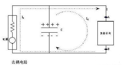
At 13:17 on January 5, 2019, the charging and discharging of the upper decoupling capacitor makes the power supply voltage obtained by the integrated circuit relatively stable and reduces the voltage oscillation phenomenon; Integrated circuits can absorb or release current on their decoupling capacitors nearby, and it is not necessary to obtain current from a distant power supply through the power line, so the speed of integrated circuits will not be affected; At the same time, decoupling capacitors provide their own nearby high-frequency channels for the transient changing current of integrated circuits, which greatly reduces the outward radiation noise and there is no common impedance between them, so the common impedance coupling is suppressed.
Since the impedance of the decoupling capacitor at high frequency will be reduced to its self resonant frequency, the high-frequency noise in the signal line can be effectively removed, and at the same time, compared with the low frequency, it has no impact on the energy, so a suitable decoupling capacitor can be added between the power feet of each integrated circuit. When choosing the type of decoupling capacitor, which high-frequency capacitors with low inductance should be considered. Such as multilayer ceramic capacitors or monolith capacitors with good high-frequency performance.
In digital circuits, when the circuit changes from one state to another, a large peak current will be generated on the power line, forming a transient noise voltage, which will affect the normal operation of the previous stage. This is coupling. For devices with weak noise ability and large current change during shutdown, and memory devices such as ROM and ram, decoupling capacitors should be directly connected between the power line (VCC) and ground line (GND) of the chip.
The typical decoupling capacitance value in a digital circuit is 0.1 µ F. The typical value of the distributed inductance of this capacitor is 5 µ H. The decoupling capacitor of 0.1 µ f has a distributed inductance of 5 µ h, and its parallel resonance frequency is about 7MHz, that is, it has a good decoupling effect for noise below 10MHz, and has little effect on noise above 40MHz. The capacitance of 1 µ F and 10 µ f has a parallel resonance frequency above 20MHz, and the effect of removing high-frequency noise is better. One charge discharge capacitor or one energy storage capacitor should be added to every 10 or so integrated circuits, with an option of about 10 µ F. It is better not to use electrolytic capacitors, which are rolled up by two layers of thin films. This rolled up structure behaves as inductance at high frequency. Tantalum capacitors or polycarbonate capacitors should be used. The selection of decoupling capacitor is not strict, but c=1/f, that is, 0.1 µ f for 10MHz and 0.01 µ f for 100MHz.
Bypass capacitance is not a theoretical concept, but a frequently used practical method. In the 1950s and 1960s, the word has its own meaning, and is not used much now. Electronic tubes or transistors need to be biased, which determines the DC power supply conditions of the operating point. For example, the grid of an electron tube often requires negative pressure relative to the cathode. In order to work under a DC power supply, a resistor is connected in series to the cathode to the ground, and the plate current is used to form the positive potential of the cathode to the ground. While the grid DC grounding, this bias technology is called "self bias", but for (AC) signals, it is also a negative feedback. In order to eliminate this effect, a sufficiently large point capacitance is connected in parallel on this resistor, This is called bypass capacitance. Later, some materials extended it to similar situations.
The decoupling capacitor has two functions between the power supply and ground of the integrated circuit: on the one hand, it is the energy storage capacitor of the integrated circuit, on the other hand, it bypasses the high-frequency noise of the device. The typical decoupling capacitance value in digital circuit is 0.1 μ F。 The typical value of the distributed inductance of this capacitor is 5 μ H。 zero point one μ The decoupling capacitance of F is 5 μ The parallel resonance frequency of the distributed inductance of H is about 7MHz, that is, it has a good decoupling effect for noise below 10MHz and has little effect on noise above 40MHz. one μ F、10 μ The capacitance of F has a parallel resonance frequency above 20MHz, and the effect of removing high-frequency noise is better. One charge discharge capacitor or one energy storage capacitor should be added to every 10 or so integrated circuits, which can be selected as 10 μ About F. It is better not to use electrolytic capacitors, which are rolled up by two layers of thin films. This rolled up structure behaves as inductance at high frequency. Tantalum capacitors or polycarbonate capacitors should be used. The selection of decoupling capacitor is not strict. It can be taken as 0.1 according to c=1/f, i.e. 10MHz μ F. 100MHz takes 0.01 μ F。
Generally speaking, capacitors with UF capacity, such as electrolytic capacitors or tantalum capacitors, have large inductance and small resonant frequency, which can pass through low-frequency signals better, while for high-frequency signals, they show strong inductance and large impedance. At the same time, large capacitors can also act as local charge pools, which can reduce local interference and be coupled out through the power supply; Capacitors with a capacity of 0.001~0.1uf are generally ceramic capacitors or mica capacitors, with small inductance, high resonance frequency and small impedance to high-frequency signals. They can provide a bypass for high-frequency interference signals and reduce external coupling interference to this part
Bypass is to filter the high-frequency clutter or signal carried by the front stage or power supply; Decoupling is a "small pond" set to ensure the stable output of the positive output end (mainly for the work of the device), which ensures that the fluctuation range of the power supply will not affect the work of the circuit when other large currents work; A supplementary point is the so-called coupling: components that transmit signals between the front and rear stages without affecting each other‘s static working points at all levels
The high-frequency switching noise generated by active devices when switching will propagate along the power line. The main function of decoupling capacitor is to provide a local DC power supply to active devices to reduce the transmission of switching noise on the board and guide the noise to the ground.
Quoted from lundequan‘s "electromagnetic compatibility design at circuit board level", this paper speaks well about the use of noise coupling paths, decoupling capacitors and bypass capacitors. See.
In terms of circuits, there are always driving sources and driven loads. If the load capacitance is relatively large, the driving circuit needs to charge and discharge the capacitance to complete the signal jump. When the rising edge is steep, the current is relatively large, so the driving current will absorb a large power supply current. Due to the inductance and resistance in the circuit (especially the inductance on the chip pin, it will rebound), this current is actually a kind of noise compared with normal conditions, It will affect the normal work of the previous stage. This is coupling.
Decoupling capacitor is to play the role of a battery to meet the current change of the driving circuit and avoid mutual coupling interference.
The bypass capacitance is actually decoupled, but the bypass capacitance generally refers to the high-frequency bypass, which is to improve a low impedance leakage way for high-frequency switching noise. The high-frequency bypass capacitance is generally small, which is generally 0.1U, 0.01u, etc. according to the resonant frequency, while the decoupling capacitance is generally large, which is 10u or more, which is determined according to the distribution parameters in the circuit and the change of the driving current.
|
Disclaimer: This article is transferred from other platforms and does not represent the views and positions of this site. If there is infringement or objection, please contact us to delete. thank you!
中恒科技ChipHomeTek
|

 Service mailbox
 13823783658
 ChatNow