In the broad field of automotive electronics, the power system plays a vital role, especially in the vehicles equipped with start stop system. The system is increasingly embedded in cars, allowing the engine to shut down and restart automatically in all situations of traffic stops, traffic lights and waiting for travel. During the motor restart phase, a high current peak occurs, causing the supply voltage of 12 V to drop to half.
The consequence of doing so is that the on-board electronic equipment, such as car radio, navigation equipment, refrigeration system, ventilation system, etc., may have serious faults or even damage electronic components. The control unit (ECU) of the high-power DC-DC converter is designed to overcome this problem and can stabilize the 12 V power supply during the motor restart phase.
DC-DC converters play a major role and are also used in different types of applications, such as hybrid electric vehicles (HEV). The optimization and selection of DC / DC converter plays an important role in vehicle power management, which is driven by a set of efficiency requirements that must be met.
Efficiency of DC-DC converter
When evaluating the efficiency of a DC-DC converter, the system losses that significantly reduce the efficiency play an important role. There are two types related to system loss analysis: the loss caused by the peak current in the inductor and the so-called switching loss caused by the charging and discharging stages of the converter circuit. With regard to the loss caused by the peak current in the inductor, two leakage elements can be determined, one related to the drain source resistance of the on-off switching FET during the on period and the other related to the DC resistance of the inductor. In addition, in the discharge phase of the inductor, a power loss proportional to the discharge current may occur. The switching loss or dynamic characteristic is mainly caused by the capacitive effect of the circuit. In particular, the drain source parasitic switching capacity of FET and diode must be considered. The other loss is the energy loss caused by the loss of the inductor core, which is proportional to the switching frequency; In fact, an increase in frequency is accompanied by an increase in inductor core loss. This type of leakage is due to the material and size of the core.
Through careful selection of components and careful design of printed circuit boards to reduce parasitic components, the optimization of reducing energy loss is realized. One way to improve efficiency is to reduce the current flowing into the inductor by reducing the resistance loss of the active element and the inductor.
Many ADAS systems use 5V and 3.3V lines to power many of their internal analog and digital components; Similarly, manufacturers of these systems prefer to use a single converter in single cell and dual cell configurations. In today‘s ADAS system, the switching regulator must also be able to switch to a frequency of 2MHz or higher, instead of relying on a standard switching frequency lower than 500KHz. The main reason for this change is the need for a smaller solution while remaining above the AM band frequency to avoid potential interference.
Integrated circuit solutions
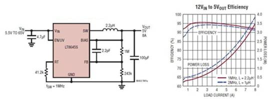
The lt8645s is a synchronous monolithic buck converter suitable for high input voltages with low EMI radiation levels. Its input voltage range of 3.4V to 65V makes it an ideal choice for applications in the automotive field, including ADAS system that must maintain stable voltage in the case of cold start and stop start. The minimum input voltage is 3.4V and the load sudden drop transient exceeding 60V (Fig. 1).
Figure 1: typical application circuit of lt8645s [source: Analog Devices]
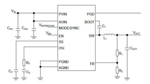
Rohm provides bd9s series (bd9s400muf-c, bd9s300muf-c, bd9s200muf-c, bd9s100nux-c, bd9s000nux-c). It is a series of secondary side synchronous DC / DC buck converters used in the automotive field, with excellent reliability, low power consumption and compact shape.
The bd9s series consists of a very compact power supply circuit, including an enabling function to adjust the start-up time, and a PGOOD output indicator to optimize the system functional safety. This broad product line supports output currents of 0.6 to 4.0 A (Figure 2).
Figure 2: typical application circuit of Rohm semiconductor bd9s series [source: Rohm semiconductor]
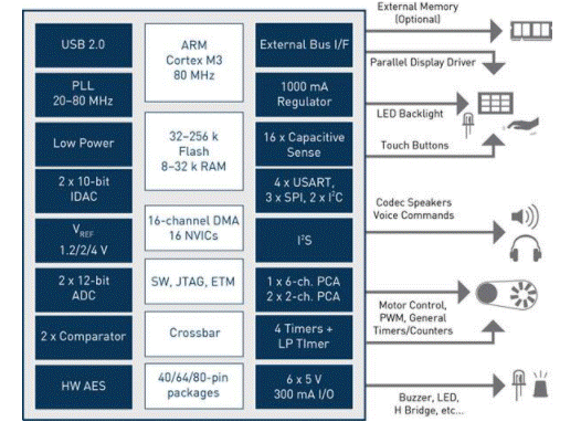
Cypress‘s s6bp20x series (s6bp201a, s6bp202a and s6bp203a) are single channel buck boost DC / DC converters suitable for automotive and industrial applications. They are ideal for automotive applications such as body control modules, instrument panels and ADAS. These pmics have low standby current and provide stable power transmission over a wide input voltage range.
Cypress‘s unique buck boost technology enables you to design smaller PMIC systems by eliminating bulky and expensive electrolytic capacitors for filtering inputs. This smaller design allows you to create a small, cost-effective energy-saving solution (Figure 3).
Figure 3: block diagram of s6bp201a
Bidirectional DC-DC
The automotive industry, especially after the recent innovation of hybrid and electric vehicles, needs to use a power system composed of multiple batteries in addition to the traditional 12 V primary battery. In addition, the use of the power regeneration system requires two-way power transmission (from the battery to the user, and vice versa).
The introduction of devices for reducing fuel consumption such as start and stop systems requires the use of two battery power supply systems. Traditional and familiar 12 V lead-acid battery with 48 V lithium battery on both sides to start the engine. Therefore, it is necessary to bi directionally transmit power between the two batteries according to the specific requirements of the entire system.
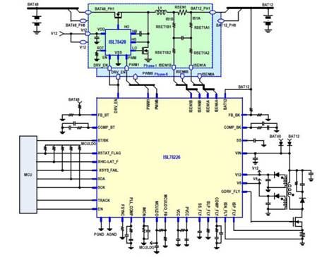
A single Rissa isl78226 device can provide a maximum power of up to 3.75 kW, with a conversion efficiency of more than 95%, and can also be integrated into a modular master / slave architecture to provide higher power. This innovative design enables designers to support the rapid adoption of a 48 V hybrid powertrain that reduces emissions and fuel consumption used in light hybrid vehicles, where the electric motor is connected to the internal combustion engine for combustion (Fig. 4).
Figure 4: typical application diagram of isl78226 [source: Risa electronics]
conclusion
The increasing popularity of hybrid electric vehicles and electric vehicles requires the use of dual battery power supply systems. Moreover, even in conventional vehicles equipped with internal combustion engines, the demand for electric power has been increasing in recent years, which is necessary to supply power to many electronic devices and accessories installed on vehicles..
|
Disclaimer: This article is transferred from other platforms and does not represent the views and positions of this site. If there is infringement or objection, please contact us to del
中恒科技ChipHomeTek
|

 Service mailbox
 13823783658
 ChatNow