The switching ripple must exist in theory and in practice. There are five ways to suppress or reduce it:
1. Increase inductance and output capacitance filtering
According to the formula of switching power supply, the current fluctuation in the inductance is inversely proportional to the inductance value, and the output ripple is inversely proportional to the output capacitance value. The ripple can be reduced by increasing the inductance value and the output capacitance value.
The above figure shows the current waveform in the inductor L of the switching power supply, and the ripple current △ I can be calculated by the following formula:
It can be seen that increasing the L value or increasing the switching frequency can reduce the current fluctuation in the inductor.
Similarly, the relationship between output ripple and output capacitance: vripple = IMAX / (CO) × f)。 It can be seen that increasing the output capacitance value can reduce the ripple.
The common practice is to use aluminum electrolytic capacitors for output capacitors to achieve large capacity. However, the electrolytic capacitor is not very effective in suppressing high-frequency noise, and the ESR is relatively large, so a ceramic capacitor will be connected in parallel to it to make up for the shortage of aluminum electrolytic capacitor.
At the same time, when the switching power supply operates, the voltage Vin at the input terminal does not change, but the current changes with the switch. At this time, the input power supply will not provide current well. Usually, the parallel capacitor is used to provide current near the current input terminal (in the case of Buck type, it is near the switch h).
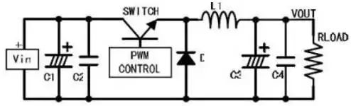
After this countermeasure is applied, Buck type switching power supply is as shown in the following figure:
The above method has limited effect on reducing ripple. Because of the volume limitation, the inductance will not be large; When the output capacitance is increased to a certain extent, there is no obvious effect on reducing ripple; Increasing the switching frequency will increase the switching loss. Therefore, when the requirements are relatively strict, this method is not very good.
For the principle of switching power supply, please refer to various switching power supply design manuals.
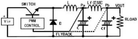
2. Second stage filtering, i.e. adding Yi stage LC filter
LC filter has obvious suppression effect on noise ripple. Selecting appropriate inductance and capacitance to form a filter circuit according to the ripple frequency to be removed can generally reduce the ripple. However, in this case, it is necessary to consider the sampling point of the feedback comparison voltage. (as shown in the figure below)
After LDO, the switching ripple is generally below 10mV.
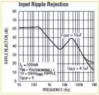
The following figure shows the comparison of ripple before and after LDO:
Comparing the waveform in the graph above with the waveform in the graph on the left, it can be seen that the LDO has a very good suppression effect on the switching ripple of several hundred kHz. But in the high frequency range, the effect of the LDO is not so ideal.
To reduce ripple. The PCB wiring of switching power supply is also very critical, which is a very difficult problem. There is a special switch power supply PCB engineer. For high-frequency noise, because the frequency is high and the amplitude is large, the post filter has a certain effect, but the effect is not obvious. There are special studies in this area. The simple way is to connect the capacitor C or RC on the diode, or connect the inductor in series.
For high-frequency noise, since the frequency is high and the amplitude is large, the post filter has a certain effect, but the effect is not obvious. There are special studies in this area. The simple way is to connect the capacitor C or RC on the diode, or connect the inductor in series.
4. On the diode and capacitor C or RC
Parasitic parameters should be considered when the diode is turned on and off at high speed. During the reverse recovery of the diode, the equivalent inductance and the equivalent capacitance become an RC oscillator, generating high-frequency oscillation. In order to suppress this high-frequency oscillation, a capacitor C or RC buffer network should be connected in parallel at both ends of the diode. The resistance is generally 10 Ω - 100 Ω, and the capacitance is 4.7pf-2.2nf.
The value of the capacitor C or RC connected in parallel with the diode can be determined after repeated tests. If it is not selected properly, it will cause more serious oscillation.
If high-frequency noise is strictly required, soft switching technology can be used. There are many books about soft switches.
5. Inductor after diode (EMI filter)
This is also a commonly used method for suppressing high-frequency noise. Selecting an appropriate inductance element for the frequency at which noise is generated can also effectively suppress noise. It should be noted that the rated current of the inductor should meet the actual requirements.
Summary
The above is about the ripple of switching power supply. It is better to add some waveforms. Although it may not be complete, it is sufficient for general applications. As for noise suppression, it may not be all applied in practice. It is important to select appropriate methods according to your own design requirements, such as product volume, cost, development cycle, etc.
|
Disclaimer: This article is transferred from other platforms and does not represent the views and positions of this site. If there is infringement or objection, please contact us to del
中恒科技ChipHomeTek
|

 Service mailbox
 13823783658
 ChatNow