With the development of urban economy, the harm caused by inductive lightning and lightning wave has increased greatly. The lightning rod on the general building can only prevent direct lightning, while the induced lightning and pulse voltage generated by the strong electromagnetic field can sneak into the room and endanger the electric equipment such as TV, telephone and electronic instrument. Especially for the solar control instrument, due to the special situation of the solar installation position, its use stability has been the focus of the majority of developers. Lightning surge of instantaneous high voltage and signal system surge are important reasons for poor instrument stability. The main sources of surge voltage of signal system are induced lightning strike, electromagnetic interference (EMI), radio interference and electrostatic interference. Metal objects (such as telephone lines) are affected by these interference signals, which will cause errors in the data in transmission and affect the accuracy and transmission rate of transmission. How to design lightning protection circuit becomes the key problem of instrument development.
1 lightning surge analysis
The most common hazards of electronic equipment are not caused by direct lightning strikes, but by current surges induced in power supply and communication lines when lightning strikes occur. On the one hand, due to the highly integrated internal structure of electronic equipment (VLSI chip), the level of withstand voltage and overcurrent of the equipment decreases, and the ability to withstand lightning (including induced lightning and operating overvoltage surge) decreases. On the other hand, due to the increase of signal source paths, the system is more vulnerable to lightning wave invasion than before. Surge voltage can enter computer equipment through power line or signal line. We will discuss these two aspects separately:
1.1) power surge
Power surge does not only originate from lightning strikes. When short-circuit fault occurs in the power system and large load is switched on and off, power surge will occur. The power grid stretches for thousands of miles. The probability of occurrence of lightning strikes or line surges is high. When a lightning strike occurs hundreds of kilometers away from you, the lightning surge is transmitted through the speed of light of the power grid and attenuated by the substation. When it reaches your computer, there may still be thousands of volts. This high voltage is very short, only a few tens to hundreds of microseconds, or not enough to burn the computer, but it has great damage to the semiconductor components inside the computer, just as the noise of the old audio is greater than that of the new one because the internal components are damaged, With the deepening of these damages, the computer becomes more and more unstable, or it may cause the loss of your important data. GE company of the United States measured that the number of surge voltages exceeding the original working voltage by more than one time occurred in the low-voltage distribution lines (110V) of ordinary families, hotels, apartments, etc. within 10000 hours (about one year and two months) reached more than 800 times, of which more than 300 times exceeded 1000V. Such surge voltage may damage the electronic equipment at one time.
1.2) signal system surge
The main sources of surge voltage of signal system are induced lightning strike, electromagnetic interference, radio interference and electrostatic interference. Metal objects (such as telephone lines) are affected by these interference signals, which will cause errors in the data in transmission and affect the accuracy and transmission rate of transmission. Eliminating these interferences will improve the transmission condition of the network.
Based on the above technical defects and conditions, this paper designs a single-phase parallel lightning surge resistant switching power supply circuit based on varistors and ceramic gas discharge tubes.
2 design of lightning surge protection circuit
This paper designs a single-phase parallel anti lightning surge circuit based on varistor and ceramic gas discharge tube, and applies it to the switching power supply of instrument. The whole circuit includes lightning protection circuit and switching power supply circuit, wherein the lightning protection circuit is composed of three varistors and a ceramic gas discharge tube, and the common mode and differential mode are fully protected. The power supply circuit of the lightning protection instrument is composed of the classic switching power supply circuit. The varistor is used in parallel to extend the service life. After the short-circuit failure of the varistor, it is separated from the switching power supply circuit and will not cause fire.
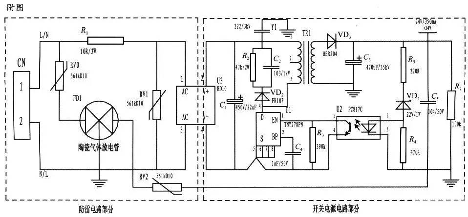
In order to achieve the above objectives, the design scheme adopted is to apply the single-phase parallel lightning surge resistance circuit of varistor and ceramic gas discharge tube to the power supply of the instrument. It is mainly divided into lightning protection circuit part and switching power supply circuit part. The circuit is simple. It adopts compound symmetrical circuit, common mode and differential mode full protection, and can be connected without L and n terminals. The varistor rv1 is located at the front end of the patch rectifier module and connected in parallel with the power supply L and N respectively, mainly to clamp the voltage between the L and N lines. The varistors rv0 and RV2 are connected in series with the ceramic gas discharge tube FD1 and grounded. The series connection of rv0 and FD1 is mainly to discharge the lightning surge current induced on the L line. The series connection of RV2 and FD1 is mainly to discharge the energy on the 24V reference potential connected by the signal port. After the short-circuit failure of rv0 and RV2, FD1 can separate them from the power supply circuit, No fire will occur. A wire wound resistor is connected in series on the front-end line of rv1. When the rv1 short circuit fails, the wire wound resistor can act as a fuse to disconnect the short circuit circuit circuit. The varistor is a voltage clamp type protection device, and the selection of its clamp voltage point, i.e. the parameter of the varistor, is relatively important (the one with higher pressure-sensitive voltage and larger flux is safer, more durable and has a low failure rate); The overall size and packaging form are selected according to the requirements of current capacity. In this circuit, 561k-10d varistors and ceramic gas discharge tubes are connected in series to prolong the service life and ensure safety. The flow capacity of the ceramic gas discharge tube is selected according to the required flow capacity. The circuit adopts 3rm470l-7.5-l and the flow rate is 5000A. The wire wound resistor R1 serves to limit the current and divide the voltage; The chip mounted rectifier module is the front-end rectifier of the switching power supply circuit, C1 is the high-voltage filter capacitor, Y1 is the decoupling capacitor, the resistor R2, the capacitor C2 and VD2 constitute the absorption clamp circuit of the MOS tube of the switching power supply chip, and the protection chip. The switching power supply chip adopts the tny27 series of PI company, Tr1 is the high-frequency transformer, VD3 and C3 constitute the secondary filter of the high-frequency transformer, U2, VD4, R3, R4 and R5 constitute the feedback circuit of the switching power supply circuit, The secondary output voltage of the transformer can be stabilized at the design value, and the lightning protection and anti surge circuit has achieved good results in practical use.
3 concluding remarks
The single parallel lightning protection circuit based on varistors and ceramic gas discharge tubes is gradually favored by the majority of designers in the development of solar control instruments in recent years. The circuit designed in this paper is rigorous and fully conforms to the test standard of GB / T 17626.5. In actual use, the space of PCB board can be vacated to provide developers with a design stage at will.
|
Disclaimer: This article is transferred from other platforms and does not represent the views and positions of this site. If there is infringement or objection, please contact us to del
中恒科技ChipHomeTek
|

 Service mailbox
 13823783658
 ChatNow