Oscilloscope is an indispensable test equipment in electronic circuit detection. It can depict the specific image waveform of very abstract and invisible periodic signal or signal state change process on the fluorescent screen. It can measure various circuit parameters, such as voltage, current, frequency, phase and other electrical quantities. It has the characteristics of high input impedance, good frequency response and high sensitivity. The following takes mos-620 dual trace oscilloscope as an example to introduce the use of oscilloscope in detail. Fig. 1-4-1 is a schematic diagram of mos-620 dual trace oscilloscope panel.
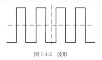
1. Functions of the panel and knobs the panel layout can be divided into four parts: A. display screen (located on the left side of the panel) (1) cal calibration signal output terminal; Provide 1kHz ± 2% and 2Vp-p ± 2% square wave signals for Y-axis and X-axis calibration. (2) Brightness knob (in ten); Adjust the brightness of the light track, and rotate clockwise to increase the brightness. (3) Focus knob (focus); Adjust the clarity of the track or bright spot. (4) Trace rotation; A semi fixed potentiometer is used to adjust the horizontal track and the level of the scale line. (5) Power indicator: the indicator lights up when the power is on. (6) Power switch: pop up the power switch button to the "off" position. Connect the power cord, press the power cord, press the power switch key, and turn on the power. (33) display screen: display the measured voltage waveform, and the upper grid is convenient for reading during measurement. B. Vertical direction part (located at the lower right) (8) ch1 (x) input: used for input in the vertical direction. In the X-Y mode, it is used as the x-axis input terminal. (20) CH2 (y) input: the same as ch1, but in X-Y mode, it is used as the y-axis input terminal. (10)、(18)AC-GND-DC; Select the input mode of the vertical input signal. Alternating current (AC); The vertical input terminal and the signal are capacitively coupled; Grounding (GND); The vertical input terminal and the signal are capacitively coupled; Grounding (GND); Internal grounding of vertical input terminal: DC; The vertical input terminal is DC coupled with the signal. (7) , (22) vertical fine adjustment switch (volts / div); Used to select vertical deflection coefficient, from 5mv / div to 5V / div, 10 gears in total. (9) , (21) vertical fine tuning switch (vabible): used to continuously change the sensitivity of vertical deflection. In the calibration position, the sensitivity is calibrated to the identification value. When the knob is pulled out (x5mag state), the signal in the vertical direction is expanded by 5 times. (11) , (19) vertical displacement (position); Adjust the vertical position of the light trace in the screen. (14) Vertical mode: select the ch1 and CH2 working modes (vertical mode) Ch1 or CH2; Channel 1 or channel 2 is displayed separately. DUAL; Both channels are displayed at the same time. Add: displays the algebraic sum (ch1 + CH2) of the two channels. Press ch2inv (16) to display the algebraic difference (ch1-ch2) (12) Alternate display (ALT / chop): when double track display is used, this key pops up, indicating that channel 1 and channel 2 are alternately displayed (usually used when the scanning speed is high): when this key is pressed, channel 1 and channel 2 are intermittently displayed at the same time (usually used when the scanning speed is low). (16) Signal inversion (ch2inv): the signal of channel 2 is inverted. When this key is pressed, the signal of channel 2 and the trigger signal of channel 2 are reversed at the same time. C. Horizontal (29) horizontal scanning speed switch (time / div); The scanning speed can be divided into 20 gears, from 0.2us/div to 0.5s/div When it is used to measure the period of waveform, it is the range selection switch of time. (30) horizontal fine adjustment (variable); Fine tune the horizontal scanning time to make the display light trace size appropriate. When this knob is rotated clockwise to the end, it is in the calibration position, and the scanning speed is calibrated to be consistent with the time / div on the panel. (31) scan expansion switch; When pressed, the scanning speed is expanded by 10 times. (32) horizontal displacement knob (position); Adjust the horizontal position of the light trace on the screen. D. An external trigger input terminal of a trigger (24); For input of external trigger signal. When using this function, the switch (23) should be set at the EXT position. (23) trigger source selection switch (source); Ch1: select the input signal of channel 1 as the internal trigger signal CH2: select the input signal of channel 2 as the internal trigger signal line: select the AC power supply as the trigger signal ext: the external trigger signal is connected to (24) as the trigger signal source for triggering special signals. (27) alternate trigger (trig ALT); When double track is displayed alternately, the trigger signal comes from ch1 channel signal and CH2 channel signal respectively. This method is used to observe two unrelated signals at the same time. (26) polarity: polarity selection of trigger signal. "+" refers to rising edge trigger and "-" refers to falling edge trigger. (28) trigger level: display a synchronous and stable waveform and set the starting point of a waveform. Move up to the "+" rotation trigger level and down to the "-" rotation trigger level. (25) trigger mode: select the trigger mode. Auto: automatic. When there is no trigger signal input, the scanning is in automatic mode. Norm: normal. Scanning can only be performed when there is a trigger signal, otherwise the scanning baseline will not be displayed. When the input signal frequency is lower than 50Hz, please use the "normal" trigger mode. Tv-v: used when you want to observe the field signal waveform of the TV signal. TV-H: used when you want to observe the line signal waveform in the TV signal. (39) level lock: turn the trigger level knob (28) clockwise to the end and the trigger level will be locked at the fixed level after a "click" sound is heard. At this time, if the scanning speed or signal amplitude is changed, the synchronization signal can be obtained without adjusting the trigger level. (15) GND: grounding terminal of oscilloscope cabinet. 2. Basic operation of oscilloscope A. preparation before startup (1) display screen: the brightness knob is 1 / 3 clockwise, and the focus knob is centered. (2) Vertical direction: channel ch1, vertical displacement knob centered, ac-gnd-dc switch selected AC. (3) Horizontal direction: the horizontal displacement knob is centered, and the horizontal scanning speed switch is set to 0.5ms/div (4) Trigger part: the trigger source selection switch is set to ch1, the trigger coupling switch is set to AC, the trigger polarity switch is set to "+", the alternate trigger switch pops up, the level lock switch is pressed, and the trigger mode selection switch is set to "automatic" B Power on (1) press the power supply, the power indicator will be on, and the display will show the light trace after about 20s. If the light trace still appears after 60s, check whether the positions of all switches and knobs are correct. (2) Adjust the brightness and focus knob to make the light trace brightness moderate and clearest. (3) Adjust the ch1 vertical displacement knob to make the scanning line coincide with the horizontal center scale line. (4) Input the correction signal to the ch1 input terminal with a 10:1 probe, and the waveform shown in Fig. 1-4-2 can appear.
C. The dual channel operation changes the dual state of the vertical mode, so the light trace of channel 2 (CH2) will also appear on the screen (the same as ch1) At this time, channel 1 displays a square wave (the waveform from the calibration signal output), while channel 2 only displays a straight line, because no signal is connected to this channel. Now connect the calibration signal to the input terminal of CH2, which is consistent with ch1. Set the ac-gnd-dc switch to AC state, and adjust the vertical displacement knobs (11) and (19) to make the waveforms of the two channels as shown in Fig. 1-4-3.
Release the ALT / chop switch (put it in the alt mode), and the signals of ch1 and CH2 will be alternately displayed on the screen. This setting is used to observe two signals with short scanning time. Press the ALT / chop switch (put it in the chop mode), and the signals on ch1 and CH2 will be independently displayed on the screen at a speed of 250kHz. This setting is used to observe the two signals with long scanning time. In case of dual channel operation (dual or addition / subtraction mode), the signal of channel 1 or channel 2 must be selected as the trigger signal through the switch of the trigger signal source. If the signals of ch1 and CH2 are synchronized, the two waveforms will be stably displayed; otherwise, only one channel as a trigger signal can be stably displayed; if the trig / ALT switch is pressed, both waveforms will be stably displayed at the same time. D. Probe calibration oscilloscope probes can be used in a wide frequency range, but phase compensation must be performed. Therefore, before measurement, the probe shall be calibrated. Connect the 10:1 probe BNC to the input end of ch1 or CH2, set the attenuation switch to about 50mV, connect the probe of the probe to the output end of the calibration signal, and adjust the compensation capacitance until the best square wave is obtained (no rounded corner or tilt foot), as shown in Fig. 1-4-4.

3. Measurement method using oscilloscope (1) voltage measurement generally adopts the method of directly measuring peak to peak value to measure AC voltage. The y-axis input coupling selection switch should be set to "AC". Adjust the reference line of 0V to the middle position. If the signal waveform displayed on the fluorescent screen is as shown in figure 1-4-5, the ordinate scale is 4 grids, the oscilloscope‘s volts / div (voltage attenuation) is 0.5v/div, the y-axis probe‘s attenuation coefficient is not attenuated, and the vertical fine tuning switch is in the calibration position, the peak to peak voltage of the measured signal is: peak to peak voltage = "volts / div" set value x input signal display amplitude (number of grids in the vertical direction) Vp-p = 0.5x4 = 2V

(2) The time measurement and the frequency measurement are only the general periodic measurement methods. 1) Before measurement, turn the horizontal fine adjustment knob of the oscilloscope clockwise to the end, so that the scanning speed is calibrated to be consistent with the time / div indication on the panel. 2) Access the measured signal and move the graph to the center of the fluorescent screen, as shown in figure 1-4-6.
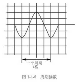
3) The period T of the read signal is 5 frames in the horizontal direction, and the time / div (horizontal scanning switch) is 0.5ms/div Cycle (T) = the set value x of "time / div" corresponds to the length of the measured time (the number of cells in a cycle in the horizontal direction) t = 0.5x4 = 2ms the reciprocal of the cycle is frequency f = 1 / T = 1 (2ms) = 500Hz (3) precautions for use 1) before the test, the square wave at the output end of the calibration signal of the oscilloscope can be used to calibrate the deflection sensitivity in the vertical direction and the scanning speed in the horizontal direction. 2) When displaying the waveform, it should not exceed the range of the fluorescent screen. 3) The peak to peak value of the test voltage shall not exceed 300V 4) The fine adjustment knob must be placed at the calibration position during quantitative observation.
|
Disclaimer: This article is transferred from other platforms and does not represent the views and positions of this site. If there is any infringement or objection, please contact us to delete it. thank you!
中恒科技ChipHomeTek
|

 Service mailbox
 13823783658
 ChatNow