The three terminal voltage stabilizing integrated circuit commonly seen in switching power supply has 78% positive voltage output?? 79% of series and negative voltage output?? Series. Therefore, the name implies that the three terminal IC means that the integrated circuit used for voltage stabilization has only three outputs, namely, the input terminal, the ground terminal and the output terminal. It looks like an ordinary triode, the standard package of the TO - 220, and the TO-92 package of the 9013.
The 78/79 series three terminal voltage stabilizing IC requires few peripheral components to form a voltage stabilizing power supply. There are also over-current, overheat and regulator protection circuits inside the circuit, which are reliable, convenient and cheap. The number after 78 or 79 in this series of integrated voltage stabilizing IC models represents the output voltage of the three terminal integrated voltage stabilizing circuit. For example, 7806 indicates that the output voltage is positive 6V, and 7909 indicates that the output voltage is negative 9V.
78/79 series three terminal regulated IC has been produced by many electronic manufacturers since 1980s, but it is still widely used in switching power supply.
Sometimes there is an M or L behind the number 78 or 79, such as 78M12 or 79L24, to distinguish the output current and packaging form. The ZD output current of the 78L series is 100mA, the ZD output current of the 78M series is 1A, and the ZD output current of the 78 series is 1.5A. It also has a variety of packages, as shown in Figure. The plastic encapsulated voltage stabilizing circuit has the advantages of easy installation and low price, so it is used more frequently. The output voltage of 79 series is negative. The naming method and shape of the pins are the same as those of the 78 series except that they are arranged differently.
Because the three terminal fixed integrated voltage stabilizing circuit is easy to use, it is often used in electronic production, which can be used to modify the voltage stabilizing power supply of discrete components, and also often used as the working power supply of electronic equipment. The circuit diagram is shown in the figure.
Note that the input, output and grounding terminals of the three terminal integrated voltage stabilizing circuit must not be connected incorrectly, or they will be easily burned out. Generally, the ZX input and output voltage difference of the three terminal integrated voltage stabilizing circuit is about 2V, otherwise it cannot output a stable voltage. Generally, the voltage difference should be kept at 4-5V, that is, the voltage after transformer transformation, diode rectification and capacitor filtering should be higher than the voltage stabilizing value.
In practical application, a sufficiently large radiator should be installed on the three terminal integrated voltage stabilizing circuit (of course, it is not necessary under the condition of small power). When the temperature of the voltage stabilizing tube is too high, the voltage stabilizing performance will become poor, or even damaged.
When a regulated power supply capable of outputting current of more than 1.5A is required in production, several three terminal regulated circuits are usually used in parallel to make its ZD output current N 1.5A. However, attention should be paid to the application: integrated regulated circuits used in parallel should be products of the same manufacturer and batch number to ensure the consistency of parameters. In addition, a certain margin is left on the output current to avoid the chain burning of other circuits when individual integrated voltage stabilizing circuits fail.
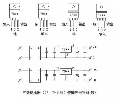
TO-220 and TO-202 packages are commonly used in 78 * * and 79 * * series three terminal regulators. The figures, pin numbers and pin functions of the two packages are shown in the figure. The pin number marking method in the figure is in the order of pin potential from high to low. This marking is convenient for memory. Pin ① is Z high potential, pin ③ is Z low potential, and pin ② is centered. It can be seen from the figure that pin ② is the output terminal regardless of positive pressure or negative pressure. For 78 * * positive pressure series, the input is Z high potential, naturally ① pin, and the ground terminal is Z low potential, i.e. ③ pin, as shown in the figure. For 79 * * negative pressure series, the input is Z low potential, which is naturally pin ③, while the ground end is Z high potential, which is pin ①, as shown in the figure. In addition, it should be noted that the heat sink is always connected to the ③ pin of Z low potential. In the 78 * * series, the heat sink is connected to the ground, while in the 79 * * series, the heat sink is connected to the input terminal.
|
Disclaimer: This article is transferred from other platforms and does not represent the views and positions of this site. If there is any infringement or objection, please contact us to delete it. thank you!
中恒科技ChipHomeTek
|

 Service mailbox
 13823783658
 ChatNow