At first, driving the motor seems to be a simple task - just connect the motor to the appropriate voltage rail, and it will start to rotate. But this is not the perfect way to drive the motor, especially when other components are involved in the circuit. Here, we will discuss one of the most common and effective methods to drive DC motor - H-bridge circuit.
Motor drive
The most common type of motor you may encounter in the enthusiast community for low power applications is the 3V DC motor shown below. This motor is optimized for low voltage operation with two 1.5V batteries.
Running it is as simple as connecting it to two batteries - as long as the batteries are connected, the motor starts and runs immediately. Although this setting is suitable for "static" applications such as micro windmills or fans, "dynamic" applications such as robots require higher accuracy in the form of speed change and torque control.
It is obvious that reducing the voltage at both ends of the motor will reduce the speed, and the battery failure will cause the motor speed to slow down. However, if the motor is powered by a track shared by multiple equipment, an appropriate drive circuit is required.
This can even take the form of a variable linear regulator (such as LM317) - the voltage at both ends of the motor can change to increase or decrease the speed. If more current is needed, the circuit can be carefully constructed with several bipolar transistors. The biggest disadvantage of this setup is efficiency - just like any other load, transistors consume all the unwanted power.
The solution to this problem is a method called PWM or pulse width modulation. Here, the motor is driven by a square wave with an adjustable duty cycle (ratio of on time to signal period). The total power transmitted is proportional to the duty cycle. In other words, the motor is energized only for a small part of the time - so the average power of the motor decreases over time. When the duty cycle is 0%, the motor is closed (no current flow); When the duty cycle is 50%, the motor operates at half the power (half of the current consumption), and 100% represents the full power at the maximum current consumption.
This is achieved by connecting the high end of the motor and using N-channel MOSFET drive, which is again driven by PWM signals.
This has some interesting implications - the 3V motor can be driven with a low duty cycle using a 12V power supply because the motor only sees the average voltage. By careful design, no separate motor power supply is required.
What if we need to reverse the direction of the motor? This is usually done by switching the motor terminals, but it can also be done electrically.
One option is to use another FET and a negative power supply to switch directions. This requires one terminal of the motor to be permanently grounded while the other terminal is connected to a positive or negative power source. Here, MOSFET functions like SPDT switch.
However, there are more elegant solutions. H-bridge motor drive circuit
This circuit is called the H-bridge because the MOSFET forms two vertical strokes and the motor forms a horizontal stroke of the letter "H". It is a simple and elegant solution to all motor drive problems. It can easily change direction and control speed.
In the H-bridge configuration, only diagonally opposite MOSFET pairs are activated to control the direction, as shown in the following figure:
When a pair of (diagonally opposite) MOSFETs is activated, the motor will see the current flowing in one direction, while when another pair of MOSFETs is activated, the current flowing through the motor will reverse.
The MOSFET can be left open for full power or PWM ed for power regulation or off to stop the motor. Activating the bottom and top MOSFETs (but not both) will brake the motor.
Components required
For H-bridge
DC motor
2x IRF3205 N-channel MOSFET or equivalent
2x IRF5210 P-channel MOSFET or equivalent
2x 10K resistor (pull-down)
2x 100uF electrolytic capacitor (decoupling)
2x 100nF ceramic capacitor (decoupling)
For control circuits
1x 555 timer (any variant, preferably CMOS)
1x TC4427 or any suitable grid driver
2x 1N4148 or any other signal/ultrafast diode
1x 10K potentiometer (timing)
1x 1K resistor (timing)
4.7 nF capacitance (timing)
4.7uF capacitance (decoupling)
100nF ceramic capacitor (decoupling)
10uF electrolytic capacitor (decoupling)
Forward and reverse rotation motor drive circuit
Single channel H-bridge, continuous working current 1.5A, peak value 2.5A. SOP8 package.
CST6118 Dual channel H-bridge, continuous working current 1.5A, peak value 2.5A.SOP16 package
CST6508
Single pole double throw switch
Schematic diagram of simple H-bridge circuit
Now that we have understood the theory, it is time to build an H-bridge motor driver. The circuit has enough power to drive medium motors up to 20A and 40V, and has proper structure and heat sink. Some functions have been simplified, such as the use of SPDT switches to control direction.
In addition, for simplicity, the high-end MOSFET is a P-channel. N-channel MOSFETs can also be used with appropriate driver circuits (with bootstrap).
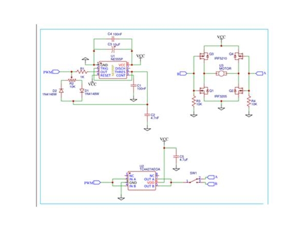
The complete circuit diagram of H-bridge using MOSFET is as follows:
Job Description
1. 555 timer
The timer is a simple 555 circuit that produces a duty cycle of approximately 10 to 90 percent. The frequency is set by R1, R2 and C2. High frequencies are preferred to reduce audible whines, but this also means that more powerful grid drivers are required. The duty cycle is controlled by potentiometer R2.
2. Grid driver
The gate driver is a standard two channel TC4427 with 1.5A sink/pull current per channel. Here, the two channels have been connected in parallel to obtain more drive current. Similarly, if the frequency is higher, the gate driver needs to be more powerful.
The SPDT switch is used to select the H-bridge arm in the control direction.
3. H-bridge
This is the working part of the circuit that controls the motor. MOSFET gates are usually pulled low by pull-down resistors. This causes both P-channel MOSFETs to open, but this is not a problem because no current can flow. When the PWM signal is applied to the gate of one leg, the N and P channel MOSFETs are alternately turned on and off to control the power.
H-bridge circuit structure skills
The biggest advantage of this circuit is that it can be extended to drive motors of all sizes, not just motors - anything else that requires a two-way current signal, such as a sine wave inverter.
Even when using this circuit at low power, proper local decoupling must be carried out, unless you want the circuit to fail.
In addition, if this circuit is built on a more permanent platform such as PCB, it is recommended to use a large ground plane to keep the low current part away from the high current path.
Therefore, this simple H-bridge circuit can solve many motor drive problems, such as bidirectional, power management and efficiency.
|
Disclaimer: This article is transferred from other platforms and does not represent the views and positions of this site. If there is any infringement or objection, please contact us to delete it. thank you!
中恒科技ChipHomeTek
|


 Service mailbox
 13823783658
 ChatNow