4、 Concept of stability
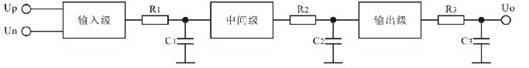
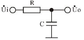
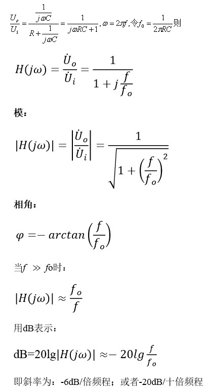
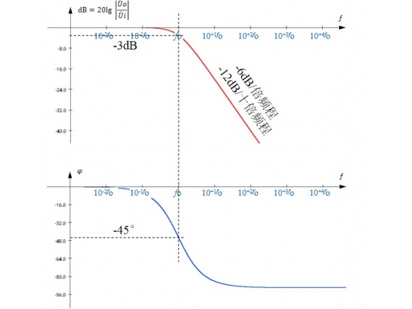
The three stages of the internal circuit of the operational amplifier will produce phase shift at a certain frequency. The more the frequency is close to or more than the characteristic frequency (fo) of the equivalent RC low-pass network of each stage of the circuit, the greater the phase shift will be generated (at the same time, the smaller the transmission coefficient of this stage).
The maximum phase shift of each stage of circuit shall not exceed 90 °
When the cumulative phase shift of the three-level circuit reaches 180 ° at a certain frequency, the output sine wave of the op amp at that frequency will be in inverse phase with the input sine wave.
Because the op amp must use negative feedback in linear applications, and the op amp is inverted at a certain frequency, at this time, the negative feedback will evolve into positive feedback at that frequency.
If AF>1 is also met at the frequency meeting the phase condition, self-excited oscillation will occur.
At this time, the linear circuit formed by the operational amplifier will not work properly—— It is called unstable.
Therefore, the stability of the op amp refers to the possibility that the op amp will not generate self-excited oscillation.
In various linear circuits composed of operational amplifiers (amplifiers, voltage followers, active filters and various operational processing circuits, etc.), whether they can work stably must be considered.
|
Disclaimer: This article is transferred from other platforms and does not represent the views and positions of this site. If there is any infringement or objection, please contact us to delete it. thank you!
中恒科技ChipHomeTek
|

 Service mailbox
 13823783658
 ChatNow