Class D power amplifier is mainly divided into half bridge, half bridge parallel, full bridge and full bridge parallel.
2.2 System structure
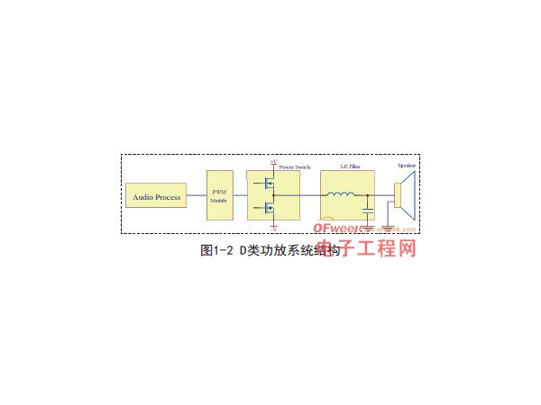
Class D power amplifier system can be divided into signal processing part, pulse width modulation part, drive part and power output part according to the structure (see Figure 1-2). The signal processing part performs noise filtering and gain adjustment. Some power amplifiers with built-in sound effects will add sound effects processing in this part. Pulse width modulation part is responsible for modulating analog audio signal into PWM signal. PWM signal amplifies PWM signal through driving circuit and power output part, and obtains the required analog amplified signal through LC low-pass filter to push the horn to make sound.
PWM signal is directly related to the distortion of analog amplifier. When other parts are the same, different modulation methods have different results, and the same modulation methods have different results under different modulation parameters.
3. PWM modulation type
PWM technology has been developed for many years and is now relatively mature. By improving the PWM part, more so-called Class E, Class G and Class T power amplifiers have been derived. As far as the basic principle is concerned, they still belong to Class D amplifier. Constant frequency pulse width regulation, due to its simple structure, has occupied a major position in the past Class D power amplifier products, especially in Class D power amplifiers with small and medium power. Self excitation pulse width modulation with feedback is mostly used on 500 watt or higher power.
3.1 Constant frequency pulse width modulation
3.1.1 Basic principle
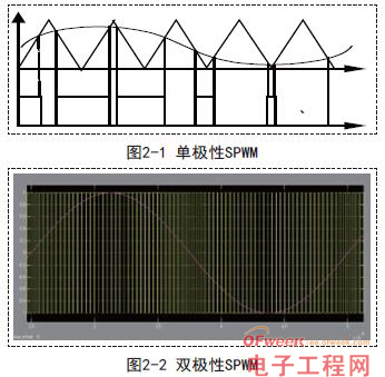
The basic principle of fixed frequency modulation is to use triangle wave as the carrier wave, input the amplified signal into the comparator for comparison, and obtain pulse waveforms with different widths but consistent periods (see Figure 1-1). This waveform contains a large number of signal spectrum components in the spectrum, which can be restored to the original signal waveform through an appropriate filter. Figure 2-1 shows the sequence waveform of bipolar SPWM modulation.
3.1.2 Application analysis
In constant frequency PWM modulation, open-loop mode is used most. Since the output signal does not participate in PWM modulation, this type of power amplifier has a simple structure and is convenient for debugging.
But the disadvantages are also obvious: because there is no feedback, the system is easy to be interfered, especially the fluctuation of power supply, which seriously restricts the performance of this kind of power amplifier. Ensuring enough stable power supply is also a necessary condition for this kind of power amplifier to obtain good performance. However, when the frequency is fixed at the high power output, higher requirements are put forward for the power output switch. There are also shortcomings in EMC: in the power spectrum of output switching noise, it is also concentrated in the odd harmonics of carrier frequency.
3.1.3 Improvement and development
Closed loop fixed frequency modulation is an improved version of open loop fixed frequency modulation. By introducing negative feedback, the dependence of power amplifier on power supply can be reduced. Due to the introduction of negative feedback, the fluctuation of the power supply within a certain range will not cause the change of the output waveform of the power amplifier. To some extent, it overcomes the defects of open-loop fixed frequency modulation and improves the distortion index of the system. However, there is still no improvement in high power output and EMC.
Adding negative feedback for modulation can improve the indicators of THD to a certain extent, but it still can not improve the EMC problem and solve the high power problem.
3.2 Closed loop frequency conversion self-excited pulse width modulation
3.2.1 Basic principle
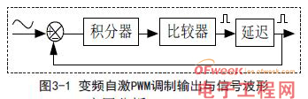
The basic principle of frequency conversion self-excited modulation is that the output signal of negative feedback system follows the input signal, and the approximate PWM waveform is output through integral delay and comparator shaping. With the change of the input signal, the duty cycle of the PWM waveform output in this way changes as well as the input cycle. Since more time is needed to offset the error in the large signal integration process, the extension of the integration cycle leads to a lower PWM frequency.
3.2.2 Application analysis
Single closed loop frequency conversion self-excited modulation uses feedback loop combined with operational amplifier and comparator to generate PWM waveform through system closed loop self-excited mode. Since PWM signal waveform is generated by self-excited mode, PWM controller is omitted. The negative feedback participates in PWM modulation, which makes it have a congenital advantage of high fidelity. At the same time, due to the continuous increase of the signal and the enhancement of the feedback depth, the carrier frequency keeps decreasing, reducing the switching frequency. Compared with fixed frequency PWM, the switching loss decreases with the decrease of switching frequency. On the premise of the same output power, this PWM modulation mode can reduce the requirements for MOSFET and radiator, and the cost is also well controlled.
Therefore, this modulation mode is widely used in high-power (300W) power amplifier products. As the output waveform is an AC signal, the carrier frequency will change with the fluctuation of the waveform. The carrier frequency will fluctuate in a large range (such as 200-400kHz), and the noise frequency of EMC will be evenly distributed in a certain area. Therefore, the problems of EMC have also been improved. The closed-loop feedback signal can be fed back before LC filtering or from the load horn. The former system is relatively stable, and the distortion is slightly inferior. The latter may be unstable when the load changes greatly. Since the feedback signal is at the horn end, the nonlinear distortion of LC can be well suppressed, so it has advantages in distortion.
3.2.3 Improvement and development
With the increasing use of frequency conversion self excitation modulation, the corresponding optimization technology has also been developed. For example, the integration link uses a second-order integration circuit. The complexity is that the double closed-loop is the introduction of double closed-loop: it not only feeds back before LC filtering, but also includes the feedback at the horn end. The purpose of using double feedback can bring double benefits in terms of stability and fidelity. At present, it has been used in a few fever power amplifier products. Of course, double feedback has high requirements for parameter dependence and device modeling, and the accuracy of all aspects will affect the actual effect. Once this application is widely mastered by engineers and technicians, the performance of Class D power amplifier will also be comprehensively improved.
4. System simulation
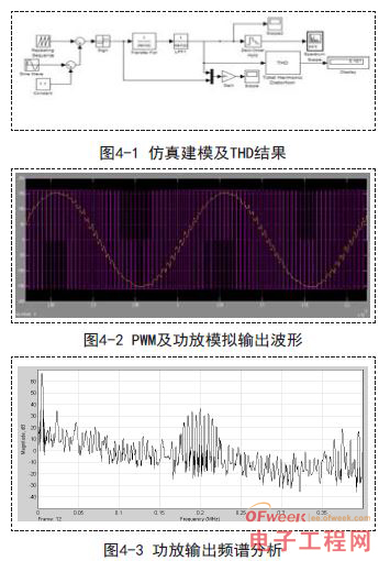
MATLAB is used for simulation. The basic simulation environment is: power supply voltage is+/- 160V, load impedance is 40ohm; 5000Hz audio signal; The modulation carrier frequency is 200k-400kHz. The filter inductance is 60uH, and the filter capacitance is 0.2uF. The main test index is THD
4.1 Constant frequency pulse width debugging simulation
4.1.1 Based on the simulation results under the 200kHz carrier and the 200kHz carrier as the simulation analysis case, the THD reaches 10% without A weighting, which can only meet the standard of entry-level power amplifier. The yellow part of the waveform line in Figure 3-2 has obvious carrier wave and high amplitude. In Figure 3-3, the energy spectrum at the 200kHz position is high and concentrated, and there are many problems in terms of EMC, except for the 30dB.low signal waveform.
4.1.2 Simulation results and analysis based on 200kHz carrier
As a simulation analysis case, the THD of 400kHz carrier is 2.8% without A weighting. This indicator can meet the use requirements of most home power amplifiers, but it cannot be applied to professional power amplifiers. The carrier peak value is 40dB lower than the signal amplitude
After the carrier frequency is increased, both the distortion and EMC are improved to a higher extent. It can be concluded that the use of higher frequency carriers will further improve the performance of the power amplifier. However, high frequency carriers require higher and faster devices, which will encounter the problem of substantial cost increase under the existing technology, and high-power high-speed devices are more difficult to grow.
4.2 Closed loop self-excited variable frequency pulse width modulation
The comparator delay shall not be higher than 30ns. The simulation results under no-load 400kHz carrier and full load 200kHz:
In the closed-loop self-excited modulation mode, the frequency range moves between 200-400kHz, and the THD reaches 0.7% without A-weighting. When A-weighting is added in practical applications, the THD can be lower than 0.1%, which can meet the requirements of professional HIFI power amplifiers. The carrier spectrum is allocated to each frequency band, and the amplitude is 55 dB lower than the signal amplitude. The effect is ideal.
5. Conclusion
Constant frequency pulse width modulation has simple structure, low application cost and can meet the requirements of most ordinary users. The structure of self-excited frequency conversion PWM is complex, and it has higher advantages in performance, especially in high-power power amplifier. The best combination point of technology and application is to select the most suitable one according to user needs and application fields.
|
Disclaimer: This article is transferred from other platforms and does not represent the views and positions of this site. If there is any infringement or objection, please contact us to delete it. thank you!
中恒科技ChipHomeTek
|


 Service mailbox
 13823783658
 ChatNow