Hot KeyWords:CST8002D  CST6118  CST6508  XS9971   CST118S  CST2466  矽源特科技

Technology Exchange
You are here : Technology Exchange

Introduction to sine wave control of brushless DC motor

Views:79Time:2023-02-01
   The sine wave control of brushless DC motor is to apply a certain voltage to the motor winding to make the motor winding produce sinusoidal current, and control the motor torque by controlling the amplitude and phase of the sinusoidal current. Compared with the traditional square wave control, the motor phase current is sinusoidal, and changes continuously without sudden change of commutation current, so the motor running noise is low.
    According to the complexity of control, the sine wave control of DC brushless motor can be divided into simple sine wave control and complex sine wave control.
01 Simple sine wave control
    Apply a certain voltage to the motor winding to make the motor phase voltage a sine wave. Since the motor winding is an inductive load, the motor phase current is also a sine wave. The phase and amplitude of the current are controlled by controlling the amplitude and phase of the motor phase voltage, which is a voltage loop control and is relatively simple to realize.
02 Complex sine wave control
    Different from the simple sine wave control, the complex sine wave control target is the motor phase current. The current loop is established to control the motor by directly controlling the phase and amplitude of the phase current. Because the phase current of the motor is a sinusoidal signal, the current decoupling operation is required, which is relatively complex. The common operations are field oriented control (FOC) and direct torque control (DTC).
The following describes the principle and implementation of simple sine wave control.
Simple sine wave control principle
     Simple sine wave control is to control the motor current by controlling the amplitude and phase of the sine phase voltage of the motor. Usually, sine phase voltage is generated at both ends of the winding by applying a certain form of voltage to the motor terminal wire. Common generation methods are sinusoidal PWM and space vector PWM. Because the sine PWM principle is simple and easy to realize, it is usually used as the PWM generation mode in simple sine wave control. Figure 1 shows the BLDC control structure diagram, where Ux, Uy, Uz are bridge arm voltages, and Ua, Ub, Uc are phase voltages of motor windings. The following descriptions of different types of PWM modulation methods will be based on this structure diagram.
Fig. 1 Control Block Diagram of DC Brushless Motor
Part 1
Three phase sine modulated PWM
    Three phase SPWM is the most common sinusoidal PWM generation method, that is, a sinusoidal voltage signal with a phase difference of 120 degrees is applied to the three terminal lines of the motor. Since the neutral point is 0, the motor phase voltage is also sinusoidal, and the phase is the same as the applied sinusoidal voltage. As shown in Figure 2.
Figure 2 Three phase modulation SPWM terminal line voltage
Part 2
Minimum switching loss sinusoidal PWM
    Different from common SPWM, when minimum switching loss sinusoidal PWM is used, the voltages Ua, Ub, Uc applied to the motor terminal line are not sinusoidal voltage. At this time, the voltage at the motor center point is not 0, but the motor phase voltage is still sinusoidal. Therefore, such control mode is line voltage control.
    Where Ux, Uy, Uz are motor terminal line voltages, Ua, Ub, Uc are motor phase voltages, and the phase difference of visible phase voltages is 120 degrees. The relationship between Ux, Uy, Uz and Ua, Ub, Uc is as follows:
After merging, Ux, Uy, Uz are as follows:


     It can be seen that when minimum switching loss sinusoidal PWM is adopted, the phase difference between Ux, Uy and Uz is 120 degrees, and it is a piecewise function, not a sinusoidal voltage, while the motor phase voltages Ua, Ub and Uc are still sinusoidal voltages. In the 120 degree area, the terminal line voltage is 0, that is, the corresponding switch tube is normally open or closed. Therefore, compared with three-phase sinusoidal PWM, the switching loss is reduced by 1/3.
    By controlling the phase and amplitude of Ux, Uy, Uz, you can control Ux, Uy, Uz to control the current.
Part 3
Space Vector Pulse Width Modulation (SVPWM)
     Different from SPWM, the voltage applied by SVPWM on the motor terminal line is not equivalent sine wave voltage. At this time, the voltage at the motor center point is not 0, but the motor phase voltage is still equivalent sine, so that the motor phase line current is also sinusoidal.
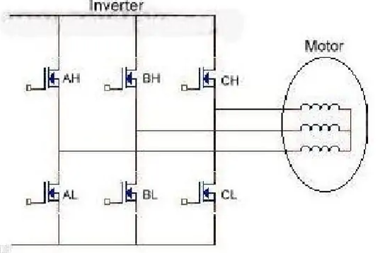
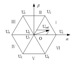
     There are eight switching modes for three-phase full bridge inverter, which correspond to eight basic voltage space vectors U0~U7 respectively. U0 and U7 are zero vectors and located at the origin. The other six non-zero vectors have the same amplitude, and the interval between adjacent vectors is 60 °. The space is divided into six sectors according to the location of the non-zero vector. Space vector pulse width modulation is to use different combinations of U0~U7 to form a reference voltage vector Uref with the same amplitude and different phases, so as to make the vector track approach the reference circle as much as possible.
Fig. 3 Distribution of basic space vector in space
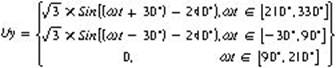
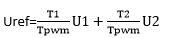
              Figure 4 shows that the reference voltage is in the first sector, and there are two non-zero vectors U1U2 and zero vectors combined. When the reference voltage enters the next sector, the new two adjacent vectors and zero vectors are combined. Based on the vector synthesis rule, under the condition that T1+T2 "=Tpwm" is met, and V1 and V2 are required to be able to synthesize vectors at any angle, so Uref_max=√ 3/2 Udc. Modulation M=Uref/(Uref_max)=Uref/(√ 3/2 Udc).
Fig. 4 Vector Synthesis Method of Reference Voltage in the First Sector
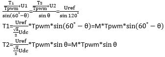
    According to the triangle sine theorem:
    θ The angle calculation method is the same as that in the previous SPWM. In order to reduce trigonometric function calculation, Sin trigonometric function table is also used in the code to obtain the best harmonic performance and minimum switching loss. At present, there are mainly 7-segment and 5-segment space vector synthesis methods.
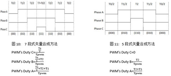
     Compared with 7-segment and 5-segment, there is a big difference in the distribution of zero vectors between them. In a single PWM cycle, the 5-segment method inserts zero vectors centrally in the middle, causing large torque ripple, which will lead to obvious walk stop instability at low frequencies. In the 7-segment method, half of the zero vectors are inserted in the middle of the PWM cycle, and the other half are inserted on both sides of the PWM cycle, which can make the operation of the flux linkage more stable, Reduce the torque ripple of the motor, so that the low frequency characteristics are obviously better than the 5-segment type, and the high frequency characteristics have little difference. However, in each PWM cycle of the 5-segment method, there is always a phase bridge arm whose switch tube state does not need to be changed. In the 7-segment method, the switch tube of each phase bridge arm needs to be switched once. The switching times of the 5-segment method are 1/3 less than those of the 7-segment method, so the switching power consumption of the 5-segment method is the minimum. In general, when the PWM cycle reaches above 10KHz, the 5-segment type is more appropriate.
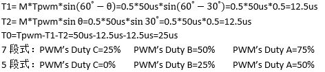
     Example: Angle θ= 30 °, torque percentage M=50%, PWM frequency 20KHz, calculate the duty cycle of each three-phase PWM.
    The above is a brief introduction to the sine wave control of DC brushless motor.


    Disclaimer: This article is transferred from other platforms and does not represent the views and positions of this site. If there is any infringement or objection, please contact us to delete it. thank you!
   
     中恒科技ChipHomeTek

Back Top