This part is roughly the smallest system of MCU, which varies according to the different MCU used. Generally, internal crystal oscillator is used. MCU with comparator and PWM timer is a better choice.
3、 Rotor position detection part
This part is a key part, which varies according to the driving methods used. The main two types are back electromotive force detection and current detection
① Back electromotive force detection
The theoretical basis of this method is that the motor will generate back electromotive force when it is running. At the zero-crossing moment of the PWM conduction device, the end voltage of the suspension phase is equal to the midpoint voltage. The hardware method can establish a virtual neutral point and end voltage comparison. In practice, most of the software sampling comparison method is used
There are three ways to use software for sampling:
1. Sampling at power-on time
When the two phases are connected, the midpoint voltage is equal to half of the bus voltage, so half of the bus voltage can be used as the reference voltage for comparison with the third phase.
The bus voltage is generally high, and the voltage after half split may be higher than the voltage borne by the MCU port. Therefore, the resistance is generally used to divide the voltage, which affects the detection sensitivity of the zero-crossing point. Moreover, because the sampling is conducted within the turn-on time, there must be a minimum turn-on time, and the low-speed operation of the motor is limited
2. Sampling at the time of power tube closing
When the upper tube is turned off and the lower tube is constant on, the continuous current will flow through the lower tube diode, and the theoretical value of the midpoint voltage is 0. To improve the accuracy, the internal reference voltage of the MCU can be set to a value slightly higher than 0, such as 0.2, and then the third phase is collected and compared with this value.
This method does not require resistance voltage divider, improves detection sensitivity, and suppresses high-frequency switching interference. However, the bearing capacity of MCU port needs to be considered, and a minimum turn-off time needs to be maintained, so the PWM duty cycle cannot reach 100%
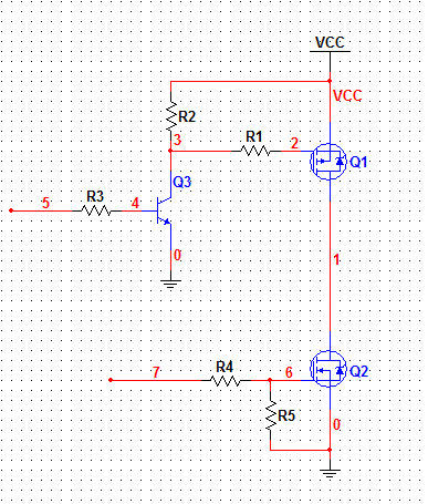
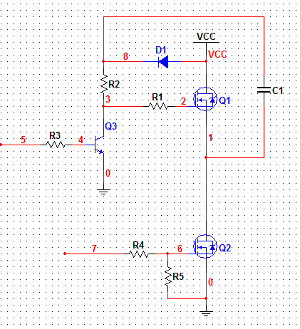
3. Sampling in full state of power tube
As shown in the figure below, this method combines the advantages of the above two methods and overcomes the disadvantages of both parties
In most practical application circuits, the first mode is adopted, as shown in the figure below. Both ends are connected to the motor three-wire and MCU respectively
② Current detection method
This method is mostly used in FOC control, as follows: connect the current sampling resistor in the three-terminal circuit, collect the phase current, and send it to MCU after amplification by the amplifier,


 Service mailbox
 13823783658
 ChatNow