The linear regulated power supply here refers to the DC regulated power supply in which the regulating tube works in a linear state. The adjustment tube works in a linear state, which can be understood as follows: RW (see the analysis below) is continuously variable, that is, linear. In switching power supply, the switch tube (in switching power supply, we generally call the adjustment tube switch tube) works in two states: on - the resistance is very small; Off - the resistance is high. The tubes working in the switch state are obviously not linear.
Linear regulated power supply is a kind of DC regulated power supply that was used earlier. The characteristics of linear regulated DC power supply are: the output voltage is lower than the input voltage; Fast response speed and small output ripple; Low noise generated by work; Low efficiency (the LDO we often see now is to solve the efficiency problem); Large heat generation (especially high-power power supply) indirectly increases thermal noise to the system.
Relevant working principles of linear stabilizer
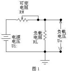
Let‘s use the following figure to illustrate the principle of voltage regulation of linear regulated power supply. As shown in the figure below, the variable resistor RW and the load resistor RL form a voltage divider circuit, and the output voltage is:
Uo=Ui × RL/(RW+RL), so the output voltage can be changed by adjusting the size of RW. Please note that in this formula, if we only look at the value change of the adjustable resistor RW, the output of Uo is not linear, but if we look at RW and RL together, it is linear. Also note that our drawing does not draw the leading-out end of RW to the left, but to the right. Although there is no difference in the formula, the drawing on the right just reflects the concepts of "sampling" and "feedback" - in fact, most of the power supply works in the mode of sampling and feedback, and the feedforward method is rarely used, or just used, and it is only an auxiliary method.
Let‘s continue: if we use a triode or field effect transistor to replace the varistor in the figure, and control the resistance of the "varistor" by detecting the output voltage to keep the output voltage constant, we will achieve the goal of voltage stabilization. This triode or field-effect transistor is used to adjust the voltage output, so it is called an adjustment transistor.
As shown in Figure 1, since the regulating tube is connected in series between the power supply and the load, it is called a series regulated power supply. Accordingly, there is also a parallel-type regulated power supply, which is to regulate the output voltage by paralleling the regulator with the load. The typical reference regulator TL431 is a parallel-type regulator. The so-called parallel connection means that, like the regulator in Figure 2, the "stability" of the emitter voltage of the attenuating amplifier tube is guaranteed by shunt. Perhaps this figure does not let you see that it is "parallel connection" at once, but it is true when you look carefully. However, you should also note that the voltage stabilizer here works in its nonlinear region. Therefore, if it is considered as a power supply, it is also a nonlinear power supply. In order to make it easier for you to understand, let‘s look back at a reasonable diagram until we can understand it concisely.
Since the regulating tube is equivalent to a resistor, the current will generate heat when flowing through the resistor, so the regulating tube working in a linear state will generally generate a lot of heat, resulting in low efficiency. This is one of the main disadvantages of linear regulated power supply. For a more detailed understanding of linear regulated power supply, please refer to the analog electronic circuit textbook. Here we are mainly to help you clarify these concepts and the relationship between them.
Generally speaking, the linear regulated power supply consists of several basic parts, such as the regulating tube, the reference voltage, the sampling circuit, and the error amplification circuit. In addition, it may also include some parts such as protection circuit and starting circuit. The following figure is a relatively simple schematic diagram of linear regulated power supply (schematic diagram, omitting filter capacitor and other components). The sampling resistance samples the output voltage and compares it with the reference voltage. After the comparison result is amplified by the error amplification circuit, the conduction degree of the adjustment tube is controlled to keep the output voltage stable.

Commonly used linear series regulated power supply chips include: 78XX series (positive voltage type), 79XX series (negative voltage type) (in actual products, XX is represented by numbers, and the output voltage is what XX is. For example, 7805, the output voltage is 5V); LM317 (adjustable positive voltage type), LM337 (adjustable negative voltage type); 1117 (low voltage differential type, there are many models, and the tail number is used to represent the voltage value. For example, 1117-3.3 is 3.3V, and 1117-ADJ is adjustable).
|
Disclaimer: This article is transferred from other platforms and does not represent the views and positions of this site. If there is any infringement or objection, please contact us to delete it. thank you!
中恒科技ChipHomeTek
|

 Service mailbox
 13823783658
 ChatNow