Hot KeyWords:CST8002D  CST6118  CST6508  XS9971   CST118S  CST2466  矽源特科技

Technology Exchange
You are here : Technology Exchange

Design of fast response feedback system for small motor drive

Views:29Time:2023-04-24
    The motor rotation information, such as position, speed and direction, must be accurate in order to produce the drivers and controllers in various emerging applications - for example, the area of the pickup and playback machine (printed circuit board) with micro components installed on the limited printed circuit board. Recently, the motor control has been miniaturized, thus realizing new applications in surgical robots for medical care and unmanned aerial vehicles for aerospace and national defense. Smaller motor controllers also support new applications in industrial and commercial facilities. The challenge faced by designers is to meet the high-precision requirements of position feedback sensors in high-speed applications, while integrating all components into a limited PCB space for installation in a miniature enclosure, such as a manipulator.
Figure 1 Closed-loop motor control feedback system. (:Analog Devices, Inc.)
Motor control
    As shown in Figure 1, the motor control circuit is mainly composed of motor, controller and position feedback interface. The motor rotates the rotating shaft to make the arm of the machine move accordingly. The motor controller tells the motor when to apply force, stop or continue to rotate. The position interface in the loop provides speed and position information to the controller. This data is critical for the correct operation of the SMT machine used to assemble miniature surface-mounted PCBs. All these applications require accurate position measurement information about rotating objects.
    The resolution of the position sensor must be very high - enough to accurately detect the position of the motor shaft, correctly pick up the tiny components, and accurately place them on the circuit board. In addition, higher motor speed will lead to higher loop bandwidth and lower delay requirements.
Position feedback system
    In low-end applications, incremental sensors and comparators may be sufficient for position sensing, while high-end applications require more complex signal chains. These feedback systems include position sensors, analog front-end signal conditioning, analog-to-digital converters (ADC) and their drivers, and then the data enters the digital domain.
    One of the position sensors is an optical encoder. The optical encoder consists of a light-emitting diode (LED) light source, a marking plate attached to the motor shaft and a photoelectric detector. The disc has a mask pattern of opaque and transparent areas, which can block light or allow light to pass through. The photoelectric detector senses the generated light and converts the on/off light signal into electrical signal.
    When the disc rotates, the photo detector and the pattern of the disc will produce mV or μ Small sine and cosine signals of V level. This system is typical in position optical encoder. These signals are fed to the analog signal conditioning circuit, usually composed of discrete amplifiers or analog programmable gain amplifiers (PGA), to increase the signal to 1 V peak to peak range - usually suitable for the dynamic range of ADC input voltage range. Then, the driver amplifier of synchronous sampling ADC will collect each amplified sine and cosine signal.
    ADC must conduct synchronous sampling on its channel to obtain sine and cosine data points at exactly the same time point, because this combination provides shaft position information. ADC conversion results are transferred to the application specific integrated circuit (ASIC) or microcontroller. The motor controller queries the encoder position at each pulse width modulation (PWM) cycle and uses this data to drive the motor according to the received command. In the past, system designers had to weigh the ADC speed or channel number to adapt to the limited occupied area of the circuit board.
Figure 2 Position feedback system. (:Analog Devices, Inc.)
Optimize position feedback
    The continuous development of technical requirements has led to the innovation of motor control applications requiring high-precision position detection. The resolution of optical encoder can be based on the number of grooves engraved with fine lithography on the optical disc, usually hundreds or thousands.
    Interpolating these sine and cosine signals into high-speed, high-performance ADC will enable us to create higher resolution encoders without making system changes to the encoder disk. For example, when the encoder sine and cosine signals are sampled at a slower rate, the captured signal values are less, as shown in Figure 3; This also limits the accuracy of the position limit.
Figure 3 Sampling rate. (:Analog Devices, Inc.)
    In Figure 3, when ADC samples at a faster rate, it will capture more detailed signal values and determine the location with higher accuracy. ADC‘s high-speed sampling rate allows oversampling to further improve noise performance and eliminate some digital post-processing requirements. At the same time, it reduces the output data rate of ADC; In other words, slower serial frequency signals are allowed to simplify the digital interface. The motor position feedback system is installed in the motor assembly, which may be very small in some applications. Therefore, the size is critical for the limited PCB area suitable for the encoder module. Multi-channel components appearing in a single micro package are suitable for saving space.
An example of position feedback design for optical encoder
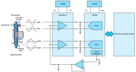
    Figure 4 shows an example of an optimized optical encoder position feedback system. The circuit can be connected to a type of optical encoder, where the differential sine and cosine signals from the encoder can be captured by the circuit. Figure 4 shows the ADA4940-2 front-end, dual-channel, full-differential amplifier that drives the ADC. In this case, the AD7380 is a dual-channel, 16-bit, full-differential, 4 MSPS, synchronous sampling SAR ADC, which is packaged in a small size of 3 mm × 3 mm LFCSP package.
Figure 4 Optimized feedback system design. (:Analog Devices, Inc.)
    On-chip 2.5 V reference will allow the component requirements of the circuit. The VCC and VDRIVE of ADC and the power rail of amplifier driver can be powered by LDO regulator, such as LT3023 and LT3032. When connecting these reference designs - for example, using a 1024 slot optical encoder, the sine and cosine of 1024 cycles are generated when the encoder disk rotates for one turn - the 16-bit AD7380 samples each encoder slot with 216 codes, which increases the overall encoder resolution by up to 26 bits.
    4 The MSPS throughput ensures that the detailed sine and cosine cycles are captured and the encoder position is correct. High throughput can realize on-chip oversampling, thus reducing the time loss of digital ASIC or microcontroller providing encoder position to the motor. On-chip oversampling allows an additional 2-bit resolution, which can be used with the on-chip resolution enhancement function. Resolution improvement can further improve the accuracy of up to 28 bits.
    The motor control system requires higher precision, higher speed and miniaturization. The optical encoder is used as the motor position sensing device. Therefore, the optical encoder signal chain must have high accuracy when measuring the motor position. High-speed and high-throughput ADC can accurately capture information and feed motor position data to the controller, thus achieving a higher level of accuracy and optimization in the position feedback system.


    Disclaimer: This article is transferred from other platforms and does not represent the views and positions of this site. If there is any infringement or objection, please contact us to delete it. thank you!
    
中恒科技ChipHomeTek

Back Top