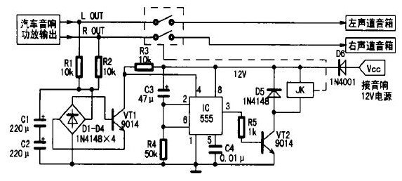
The speaker protection circuit is shown in Figure 1. It is mainly composed of midpoint potential detection circuit, delay circuit and relay. The working process of the circuit is:
Figure 1 Speaker protection circuit
1. At the moment of connecting the audio power supply, because the voltage at both ends of capacitor C3 cannot jump, it can be regarded as a short circuit, then the potential of pin ② and ⑥ of time base circuit 555 is higher than 2/3 Vcc, so 555 is in the reset state, pin ③ outputs low level, transistor VT2 is cut off, and the normally open contact of relay JK does not act. At the same time,+12 V voltage is charged to capacitor C3 through resistor R4. After a delay of about 5 s (seconds), the ② and ⑥ pin potentials of 555 are reduced to 1/3 Vcc, 555 is triggered and set, ③ pin is changed from low level to high level, transistor VT2 is connected, relay JK is powered on, and normally closed contact is closed, thus achieving a delay in connecting the speaker to the power amplifier for a period of time, completely eliminating the impact of high current on the speaker when starting;
2. When the audio power is turned off, the+12 voltage disappears quickly, but the output signal of the power amplifier does not disappear immediately, which also avoids the impact noise generated during the shutdown process;
3. When the midpoint potential is too high (higher than 1.8 V) due to abnormal operation or accidental damage of the power amplifier, the DC voltage is sent to C1, C2 filter and D1~D4 rectifier through R1 and R2 current limiting, about 1~2s (seconds), transistor VT1 is on, ④ pin of 555 changes from high level to low level, 555 is directly reset, ③ pin outputs low level, transistor VT2 is off, relay JK is powered off, normally open contact jumps, and the speaker is disconnected from the power amplifier circuit, It effectively protects the speaker from damage.
By changing the parameters of R4 and C3, you can adjust the delay time of starting the speaker protection circuit, which is generally set to 5 seconds.
2、 Component selection
555 CMOS time-base circuit with low power consumption must be selected. VT1 and VT2 use 9014 and C1815 low-power plastic encapsulated transistors, which require current amplification β> 100. D1~D5 are all 1N4148 silicon switch diodes, D6 is used for power connection reverse protection, and 1N4001~1N4007 silicon rectifier diodes can be selected. 0.5 W five-color ring metal film resistor is used for R1~R5. C1 and C2 shall use high-quality aluminum electrolytic capacitors, and C3 shall use tantalum electrolytic capacitors with small leakage and high accuracy, otherwise the delay accuracy will be affected. JK selects 12 V/7 A duplex relay (one set for left and right channels), such as JZC-22F
3、 Fabrication and commissioning
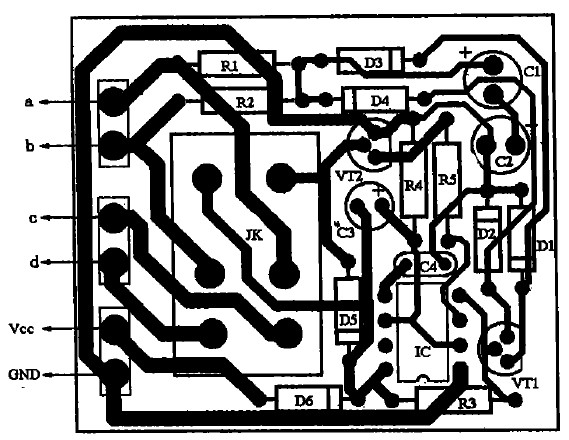
Figure 2 is a PCB diagram of speaker protection circuit. Its actual size is about 50 × 43 mm。
Figure 2 PCB board diagram
The specific production is as follows: first cut off the lead between the amplifier output end and the speaker, connect the lead heads a and b to the two sets of output ends of the amplifier respectively according to the circuit shown in Figure 2, and connect the lead heads c and d to the left and right channel speakers respectively: the power supply of the speaker protection circuit can only be obtained from the radio and the amplifier, not directly from the vehicle 12v power supply, otherwise it will not start/stop the protection function; If the radio and player equipped with diesel vehicles (using 24V power supply), it is required to add a step-down circuit (as shown in Figure 3) to supply power to the speaker protection circuit, so as not to damage the IC due to high power supply voltage.

 Service mailbox
 13823783658
 ChatNow