This article is the third in our motion control technology article series (first | second).
If you are designing motor drive applications, you may have used multiple discrete components such as bipolar junction transistors (BJTs) to achieve motor control in the past. Although this method is usually lower in cost, it uses a larger total number of components, occupies larger board space, takes longer design time, and has higher complexity. The use of multiple components may also affect system reliability.
As the complexity of applications increases, power increases, and space consumption decreases, integration becomes crucial. Integrated solutions can shorten design time, simplify procurement processes, and save costs, while also ensuring more reliable and efficient motor systems.
In this article, I will compare different motor control implementation schemes, including discrete and fully integrated options, to help you find a suitable method for your design. Table 1 compares the integration of various motor control options.
|
|
control
|
drive
|
FET
|
|
Discrete BJT
|
|
|
|
|
Gate Driver Integrated Circuit (IC)
|
|
ü
|
|
|
Motor driver IC
|
|
ü
|
ü
|
|
Integrated Control Gate Driver IC
|
ü
|
ü
|
|
|
Integrated control, gate driver, and field effect transistor (FET) IC
|
ü
|
ü
|
ü
|
Table 1: Integration degree for driving motors
Motor control using split type method
Figure 1 shows the control unit (such as a microcontroller (MCU)) processing feedback on motor status and sending signals to adjust the torque, position, and speed of the motor. The gate driver amplifies the signal from the MCU to drive the metal oxide semiconductor field-effect transistor (MOSFET) of the motor.
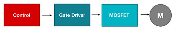
Figure 1: Basic motor control block diagram
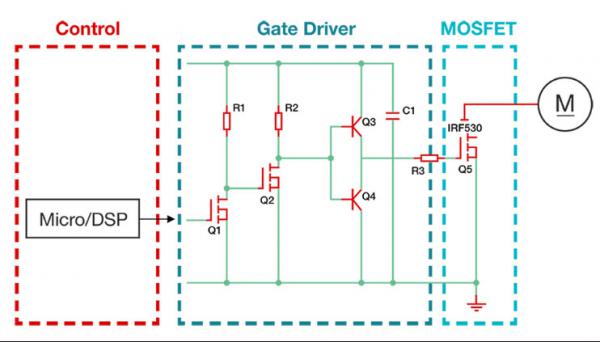
You can use the BJT totem pole/push-pull circuit as the gate drive circuit to drive a single MOSFET, as shown in Figure 2. Although this method is low-cost and easy to implement, the BJT totem pole circuit requires a large number of external components and occupies a large amount of layout space. In addition, you must replicate this discrete circuit because you need multiple MOSFETs to drive the motor, resulting in a doubling of the required number of components and board space.
Figure 2: Block diagram of gate driver implementation using discrete BJT totem pole/push-pull circuit
The first integration option: gate driver IC
The basic gate driver IC integrates the functions of totem poles into a single package. Recent technological innovations have made gate driver ICs as affordable as discrete BJTs.
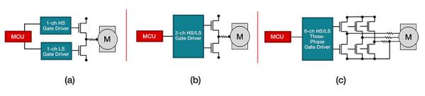
When selecting a gate driver IC, several considerations need to be considered, such as the number of channels and the voltage and current capabilities that are most suitable for the motor power level, as shown in Figure 3.
The integrated gate driver IC includes:
• Single channel gate drivers (such as UCC21732 of Texas Instruments (TI)) are usually used to drive AC motors with high side and low side high-voltage (>700V) power switches (such as insulated gate bipolar transistors (IGBT) and silicon carbide (SiC)).
Dual channel half bridge gate driver (such as UCC27712) for driving 100V to 700V motors for IGBTs and MOSFETs
• Four channel H-bridge driver and six channel three-phase motor grid driver (such as DRV8329), specially designed for low-voltage MOSFET (<60V) DC motors
As the power level of the motor changes, using gate drivers can maintain the previous design while only changing external FETs to adapt to new voltage and current levels.
Figure 3: Gate Driver IC Type for Driving External FETs
The grid driver covers the driver with basic functions (such as transconductance Undervoltage-lockout and interlock protection), and the driver with advanced functions (such as intelligent grid drive technology for slew rate control and automatic dead band control). For more information about these gate drivers, please refer to the "Understanding Smart Gate Drivers" application manual.
Traditionally, the voltage swing rate is set by the following external components: two source and drain resistors (used to limit the current of the MOSFET gate), a diode (used to adjust the rise and fall rates separately), and a pull-down resistor. With the help of intelligent gate drive technology, these components can no longer be used and the swing rate can be flexibly adjusted through serial peripheral interfaces.
The six channel driver uses intelligent grid drive technology, which eliminates the need to use up to 24 discrete components, saving space for layout and reducing the number of Bill of materials (BOM). The gate driver also integrates other protection and diagnostic functions, including current detection, overcurrent and overheating protection, fault detection, and even isolation functions, further reducing the number of components.
Second integration option: Motor driver IC
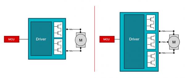
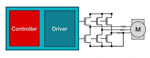
The motor driver IC includes gate drivers and integrated FETs, which are very suitable for low-power motor systems (<70W), as shown in Figure 4. Compared with gate drivers, motor driver ICs occupy less space; Integrated FET power stage, simplifying design schematic and layout. Like gate driver ICs, motor driver ICs (such as DRV8962) also integrate protection and diagnostic functions.
Figure 4: H-bridge and three-phase motor driver with integrated FET
When choosing a motor drive solution, it is important to consider the RDS (ON), peak current, and root mean square current of the internal FET. Considering the power dissipation of the internal FET, thermal calculations also need to be performed.
Third integration option: Integrated control gate driver IC
Unlike the first two options, the integrated control gate driver IC (such as MCT8329A) does not require an MCU for motor control. These ICs still have gate drivers with protection and diagnostic functions, while incorporating control algorithms without the need for MCU assistance, as shown in Figure 5.
The implementation of motor commutation algorithms may be complex, whether it is trapezoidal control, sinusoidal control, or field oriented control. The integrated control gate driver IC provides a code free solution that can handle commutation algorithms internally, helping you shorten design time and simplify the complexity of coding, debugging, and testing.
Figure 5: Integrated control three-phase gate driver
With the help of integrated control gate driver ICs, motor commutation can be flexibly achieved through sensor control or sensorless control. With the sensor control method, the external Hall effect sensor can be used to detect the rotor position; These ICs can use Hall effect sensor inputs and motor control algorithms to drive motors quietly and efficiently. In contrast, the sensorless control implementation method eliminates the need for external Hall effect sensor, thus reducing the layout space and BOM. If the sensorless integrated control grid driver IC is selected, it is necessary to measure the Counter-electromotive force (back EMF) voltage through integrated current detection and calculate the motor position internally.
Fourth integration option: integrated control, gate driver, and FET IC
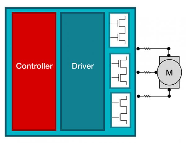
The last integration option is usually referred to as "complete integration", as shown in Figure 6. Integrated control, gate drivers, and FET ICs (such as MCF8315A) integrate drivers without code control functions, with protection and diagnostic functions, as well as FETs into one chip, resulting in smaller board space and fewer BOMs. Similar to the motor driver IC option, integrated control, gate driver, and FET IC solutions are limited by the functionality of internal FETs, requiring current and thermal calculations.
Figure 6: Fully Integrated - Motor Control, Driver, and FET
epilogue
These different levels of ICs not only meet the power level requirements of the motor, but also shorten design time, save costs, and reduce complexity. Integrated devices can also solve problems such as audible noise in household appliances and high-precision control in factory automation and robotics technology.
About Texas Instruments (TI)
Texas Instruments (TI) (NASDAQ stock code: TXN) is a global semiconductor company dedicated to designing, manufacturing, testing and selling analog and embedded processing chips for industrial, automotive, personal electronic products, communication equipment and enterprise systems. We are committed to making electronic products more economical and practical through semiconductor technology, and creating a better world. Nowadays, every generation of innovation is built on the foundation of the previous generation, making our technology smaller, faster, more reliable, and more affordable, thus achieving the widespread application of semiconductors in the field of electronic products, which is the progress of engineering. This is exactly what we have been doing for decades and even now.
|
Disclaimer: This article is transferred from other platforms and does not represent the views and positions of this site. If there is any infringement or objection, please contact us to delete it. thank you!
中恒科技ChipHomeTek
|

 Service mailbox
 13823783658
 ChatNow