Operational amplifiers are the most versatile analog devices widely used in signal conversion and conditioning, ADC sampling front-end, power supply circuits, and other applications. Although the peripheral circuit of the operational amplifier is simple, there are still many things to pay attention to during use.
1. Pay attention to whether the input voltage exceeds the limit
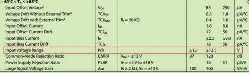
Figure 1 is a part of the input electrical characteristics in the OP07 data table of ADI. It can be seen that under the condition of a power supply voltage of ± 15V, the input voltage range is ± 13.5V. If the input voltage exceeds the range, the operational amplifier will not work properly and some unexpected situations will occur.
Some operational amplifiers do not label the input voltage range, but rather the common mode input voltage range, as shown in Figure 1-2, which is a part of TI‘s TLC2272 data table. Under the condition of a single power supply+5V, the common mode input range is 0-3.5V. In fact, due to the fact that the input voltage of the same phase and opposite phase terminals is basically the same (virtual short and virtual break) when the operational amplifier works normally, "input voltage range" and "common mode input voltage range" both have the same meaning.
Figure 1-1
Figure 1-2
2. Do not connect capacitors directly to the output of the operational amplifier
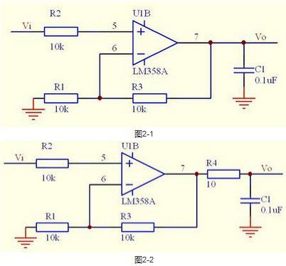
In the DC signal amplification circuit, sometimes in order to reduce the noise, the output of the operational amplifier is directly connected to the Decoupling capacitor (as shown in Figure 2-1). Although the amplified signal is a DC signal, it is very unsafe to do so. When a step signal is input or powered on, the output current of the op amp will be large, and the capacitance will change the phase characteristics of the loop, resulting in Self-oscillation of the circuit, which we do not want to see.
The correct Decoupling capacitor should form a RC circuit, that is, connect a resistance in series at the output end of the operational amplifier, and then connect the Decoupling capacitor in parallel (as shown in Figure 2-2). This can greatly reduce the instantaneous output current of the operational amplifier, without affecting the phase characteristics of the loop, and can avoid oscillation.
3. Do not connect capacitors in the feedback loop of the amplification circuit
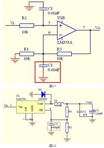
As shown in Figure 3-1, it is also a circuit used for amplifying DC signals. In order to decouple, the capacitor was accidentally connected to the feedback circuit, causing the phase of the feedback signal to change and easily causing oscillation. So, in the amplification circuit, the feedback loop cannot add any circuit that affects the signal phase. Extending this to the regulated power circuit, as shown in Figure 3-2, and connecting C3 to the feedback pin is incorrect. To reduce ripple, C3 and R1 can be connected in parallel, and the negative feedback effect of the ripple can be appropriately increased to suppress the output ripple.
4. Pay attention to the output swing of the operational amplifier
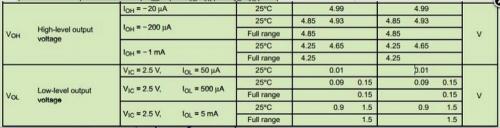
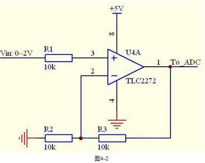
No operational amplifier can be an ideal one, and the output voltage cannot reach the power supply voltage. Generally, MOS based operational amplifiers are rail to rail operational amplifiers, which can achieve the power supply voltage under no-load conditions. However, the output will carry a certain load, and the larger the load, the more output drop. The relative value of the output amplitude of the operational amplifier based on the transistor is smaller, and some operational amplifiers have an output amplitude that is 2~6V smaller than the power supply voltage, such as NE5532. Figure 4-1 shows the output characteristics of TI‘s TLC2272 at+5V power supply. It belongs to the rail to rail operational amplifier. If this device is used as the front-end amplifier for ADC sampling (as shown in Figure 4-2), and a single power supply+5V power supply is used, then when the input approaches 0V, the input and output become nonlinear. The solution is to introduce a negative power supply, such as adding a -1V negative power supply to the 4 pins, so that the output and input are linear throughout the entire input range.
Figure 4-1
5. Pay attention to the layout of the feedback loop
The components of the feedback circuit must be close to the operational amplifier, and the PCB wiring should be as short as possible, while avoiding interference sources such as digital signals and crystal oscillators. If the layout and routing of the feedback loop is unreasonable, it will be easy to introduce noise, which will seriously lead to Self-oscillation.
6. Pay attention to power filtering
The power filter of the operational amplifier cannot be ignored, as the quality of the power directly affects the output. Especially for high-speed op amps, the power supply ripple has a great impact on the output of op amps, which will become Self-oscillation if it is not properly handled. Therefore, the best op amp filter is to add a 0.1uF Decoupling capacitor and a tens of uF tantalum capacitor near the power supply pin of the op amp, or connect a small inductance or magnetic bead in series.
|
Disclaimer: This article is transferred from other platforms and does not represent the views and positions of this site. If there is any infringement or objection, please contact us to delete it. thank you!
中恒科技ChipHomeTek
|


 Service mailbox
 13823783658
 ChatNow