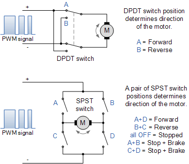
Each circuit uses a single double pole double throw (DPDT) switch to control the polarity of the motor connection. By switching contacts, the power supply to the motor terminals will reverse, and the motor will also reverse its direction. The second circuit is slightly more complex, using four single pole single throw (SPST) switches arranged in an "H" configuration.
Mechanical switches are arranged in pairs of switches and must be operated in a specific combination to operate or stop the DC motor. For example, switch combination A+D controls forward rotation, while switch combination B+C Inversion of control, as shown in the figure. Switch combinations A+B or C+D can cause a short circuit at the motor terminals, resulting in rapid braking of the motor. However, using switches in this way also carries its own dangers, as operating switches A+C or B+D simultaneously can cause a short circuit in the power supply.
Although the above two circuits can work well for most small DC motor applications, do we really want to operate different combinations of mechanical switches to reverse the direction of the motor? No! We can change the manual switches of a set of electromechanical relays and use a single forward reverse button or switch, or even use a solid-state CMOS 4066B quad bilateral switch.
But another very good way to achieve bidirectional control of the motor (and its speed) is to connect the motor to a transistor H-bridge circuit arrangement, as shown below.
Basic bidirectional H-bridge DC motor circuit
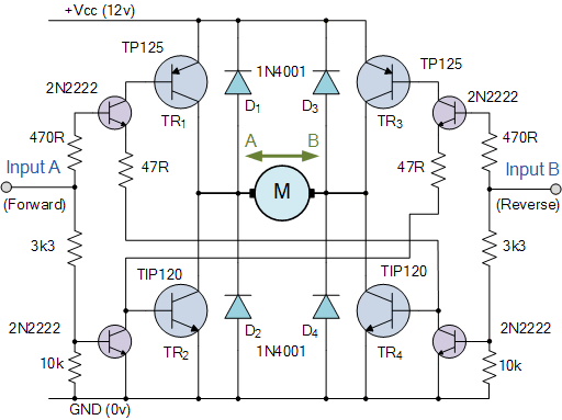
DC motor H-bridge circuit
The H-bridge circuit above is named so because the basic configuration of the four switches (electromechanical relays or transistors) is similar to the letter "H", with the motor located on the center pole. Transistors or MOSFET H-bridges may be one of the commonly used types of bidirectional DC motor control circuits. It uses a "complementary transistor pair" of NPN and PNP in each branch, where the transistors are switched together in pairs to control the motor.
Control input?? A operates the motor in one direction (i.e. forward rotation), while input B operates the motor in the other direction (i.e. reverse rotation). Then, by turning the transistors in the "diagonal pair" on or off, the direction control of the motor can be achieved.
For example, when transistor TR1 is "ON" and transistor TR2 is "OFF", point A is connected to the power supply voltage (+Vcc), and if transistor TR3 is "OFF" and transistor TR4 is "ON", point B is connected to the power supply voltage (+Vcc). 0 volts (grounded). At this point, the motor will rotate in one direction, with corresponding motor terminal A being the positive pole and motor terminal B being the negative pole.
If the switch state is reversed, TR1 is "OFF", TR2 is "ON", TR3 is "ON", and TR4 is "OFF", the motor current will flow in the opposite direction, causing the motor to rotate in the opposite direction.
Then, by applying opposite logic levels of "1" or "0" to inputs A and B, the motor rotation direction can be controlled as follows.
|
Disclaimer: This article is transferred from other platforms and does not represent the views and positions of this site. If there is any infringement or objection, please contact us to delete it. thank you!
中恒科技ChipHomeTek
|

