The step-down switching voltage regulator is a DC-to-DC converter, and is also one of the simple switching voltage regulators. When used in a Switched-mode power supply configuration, the step-down switching regulator uses a series transistor or Power MOSFET (Insulated-gate bipolar transistor or IGBT) as its main switching device, as shown below.
Step-down switch regulator
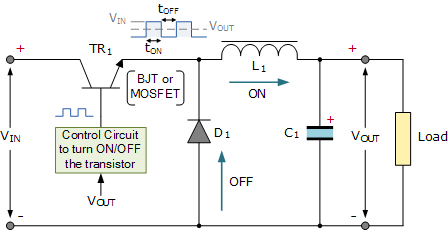
We can see that the basic circuit configuration of the buck converter is a series transistor switch TR 1 and related driving circuits (to make the output voltage as close as possible to the desired level), diode D1, inductor L1, and smoothing capacitor C1. The buck converter has two operating modes, depending on whether the switching transistor TR 1 is "on" or "off".
When the transistor is biased to "ON" (switch closed), diode D1 becomes reverse biased, and the input voltage V IN causes current to flow through the inductor to the load connected to the output end, charging capacitor C1.
When the changing current flows through the inductor coil, according to Faraday‘s law, it will produce Counter-electromotive force, which is opposite to the current flow until it reaches a stable state, generating a magnetic field L 1 around the inductor. As long as TR 1 is turned off, this situation will continue indefinitely.
When transistor TR 1 is "turned off" (switch on) through the control circuit, the input voltage immediately disconnects from the emitter circuit, causing the magnetic field around the inductor to collapse, resulting in a reverse voltage on the inductor.
This reverse voltage causes the diode to become positively biased, so the energy stored in the inductor‘s magnetic field forces the current to continue flowing through the load in the same direction and back through the diode.
Then, inductor L1 returns its stored energy to the load, acting as a power source and providing current until the energy of all inductors returns to the circuit or until the transistor switch closes again, whichever comes first. At the same time, the capacitor also discharges, providing current to the load. The combination of inductors and capacitors forms an LC filter that can eliminate any ripple generated by transistor switching actions.
Therefore, when the transistor solid-state switch is closed, the current is provided by the power supply, while when the transistor switch is open, the current is provided by the inductor. Please note that the current flowing through the inductor always flows in the same direction, directly from the power supply or through the diode, but clearly at different times during the switching cycle.
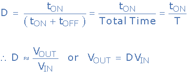
Due to the continuous closing and opening of the transistor switch, the average output voltage value will be related to the duty cycle D, which is defined as the conduction time of the transistor switch during a complete switching cycle.
If V IN is the power supply voltage and the "ON" and "OFF" times of the transistor switch are defined as t ON and t OFF, then the output voltage V OUT is:
The duty cycle of the buck converter can also be defined as:
Step-down switch regulator duty cycle
Therefore, the larger the duty cycle, the higher the average DC output voltage of the switching power supply. From this, we can also see that due to the duty cycle D never reaching 1 (unit), the output voltage will always be lower than the input voltage, resulting in a voltage drop regulator.
Voltage regulation is realized by changing the duty cycle. The switching speed is up to 200kHz, and smaller components can be used, thus greatly reducing the size and weight of the Switched-mode power supply.
Another advantage of a step-down converter is that the arrangement of inductors and capacitors (LC) can provide excellent inductance current filtering. Ideally, the step-down converter should operate in continuous switching mode so that the inductor current never drops to zero. If an ideal component is used, that is, the voltage drop and switching loss in the "on" state are zero, the efficiency of the ideal voltage drop converter can reach as high as 100%.
In addition to the step-down switching regulator used for the basic design of Switched-mode power supply, the basic switching regulator has another operation mode, that is, the step-up regulator, called the step-up converter.
|
Disclaimer: This article is transferred from other platforms and does not represent the views and positions of this site. If there is any infringement or objection, please contact us to delete it. thank you!
中恒科技ChipHomeTek
|


 Service mailbox
 13823783658
 ChatNow