In the current portable multimedia devices with centralized functions, more and more functions are being integrated into smaller and smaller systems. Audio is the most basic function of any system with multimedia function in the market, but system designers usually pay more attention to the ‘eye-catching‘ features, such as wireless connection, video processing, image capture and display. As a result, where there is a little space between many important components, the audio circuit is squeezed to where, resulting in very general or even poor audio quality. However, with a little attention, good audio quality can be seamlessly integrated into the system together with many other performances required by users. This article provides various suggestions for excellent system design and PCB layout design related to the design of any portable system with audio playback and / or recording functions.
There are many sources of poor quality audio in portable audio systems, but this paper mainly focuses on the noise sources that affect the sound quality of analog audio signals. Non harmonic noise, whether flat ("white") or tonal, can be annoying to end users. White noise is perceived as "background noise", which can be clearly heard by the user when mute, while tonal noise can be perceived as "buzzing", "humming" or "purring" according to different frequency components. Unnecessary noise pollution in audio signal can be avoided through good system design and PCB layout design.
Most portable audio systems use digital to analog converter (DAC) or codec chips to convert digital audio into analog signals that can be heard through headphones or speakers. Therefore, the layout design of audio codec or DAC is very important.
Both codec and DAC contain analog and digital circuits in the same chip. In this way, there are multiple power pins used to provide analog and digital power supplies, which are generally marked as avdd and dvdd. The reason why these power pins are separated is that the high-speed switching current of digital circuit will produce very large noise, while analog circuit is very sensitive to power noise. The key point of audio system design and layout is to provide a "clean" power supply with small ripple and transient for the analog power supply pin. Any noise present on the analog power pin will damage the quality of the audio input or output signal in different ways.
In portable audio system, the main power supply is usually battery. Due to the transient changes caused by other parts of the system (including wireless transceiver, memory and display, etc.), the noise of the battery is very large. Therefore, when providing analog power to the audio codec or DAC and other devices on the audio signal path (such as amplifiers, etc.), it is best not to directly use the battery voltage, but to use a low-voltage drop regulator (LDO) with good power supply rejection ratio (PSRR) and low output noise. This ensures that the analog circuit has a ‘clean‘ working power supply. LDO needs to be carefully selected to ensure that its rated current is sufficient to meet the needs of the supplied circuit. The use of decoupling capacitors at the analog power supply end is also important. Large decoupling capacitance (10 μ F above) very suitable for power filtering. Decoupling capacitance with small value (1 μ F below) it is also necessary to provide the fast transient current required by IC. The decoupling capacitor must be placed as close to the analog power supply pin as possible, and PCB vias must be avoided in the connection between the capacitor and the power supply and the ground as far as possible. Compared with the larger capacitance, the smaller decoupling capacitance should be placed closer to the IC pin, because the series resistance has a significant impact on the response time of the smaller capacitance.
The digital power supply of the audio converter chip is less sensitive to noise than the analog power supply, so the digital circuit can be powered by a more efficient switching mode power supply (SMPS). SMPS usually has high output ripple and noise, but their 80% efficiency and high power supply capacity can significantly prolong the battery life. Generally speaking, digital power supply does not need to use large decoupling capacitors. However, multiple 1s should be used μ Small capacitors such as F and 1NF filter the switching current with very high frequency in digital circuits. Of course, as mentioned above, smaller decoupling capacitors should also be placed closer to IC pins.
Another noise source damaging signal quality in portable audio system is noise coupled into analog input and output signals. Noise coupling mechanism can be inductive or capacitive, but excellent system design and PCB layout can reduce noise coupling. One of the ways to achieve better noise immunity is to use differential signals in the analog audio signal path as much as possible. PCB wiring used for differential signals should be wired in pairs and ensure matching impedance, so that any noise will be equally coupled into both sides of the differential signal path (i.e., ‘common mode‘ signal). The common mode suppression characteristic of the differential circuit can well suppress any coupled noise, so as to effectively reduce the audible noise volume. Although differential signals cannot be used in many cases, it is indeed a very useful means.
Another excellent system design method is to use as high a signal level as possible for the signals on the PCB that are vulnerable to noise coupling. It can be effectively assumed that the amplitude of the coupling noise will not increase with the increase of the transmission signal level. Therefore, if the noise level is constant, the signal-to-noise ratio (SNR) will increase as the signal level increases. The higher the SNR, the higher the performance of the audio system. When the low-level signal passes through the PCB, it usually needs to be amplified, which improves the noise and signal level at the same time, and finally reduces the SNR of the whole system. The best way is to amplify the low-level signal near the signal source.
Figure 1 shows an example of this approach. The 25mvp-p signal a (T) generated by the microphone must pass through the PCB and be amplified to 1Vp-p for further processing. The red box indicates the routing through PCB, which will be affected by coupling noise, and is represented by signal e (T). In scheme a, the signal is amplified before being close to the microphone, passing through the PCB and coupled to the noise. Results the SNR of the system is 60dB. In scheme B, the signal is amplified only after the wiring passes through the PCB and is coupled into the noise. As a result, the SNR of the system is only 28dB. Therefore, excellent system design can achieve significant performance improvement.
Figure 1: amplifier in different positions will produce different signal-to-noise ratio.
For signals that cannot be amplified close to the source due to system cost or volume constraints, it is important to shorten the PCB routing length as much as possible. Short PCB wiring is less susceptible to capacitive and inductive coupling noise.
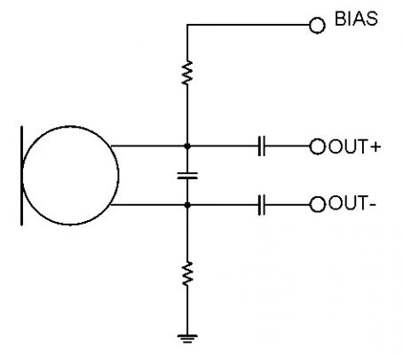
The last signal that needs to be carefully designed in a system with a built-in microphone is the microphone bias circuit. Most electret microphones (ECM) used in portable audio systems require a bias voltage of 2 ~ 3V. Usually, the bias voltage is provided by the chip away from the microphone. In this case, the bias voltage will pick up noise on the way to the microphone. This noise is directly coupled to the output of the microphone. For this, a good design method is to filter the bias voltage with resistors and capacitors near the microphone. Figure 2 is a typical microphone circuit design, which uses a ‘Pseudo differential‘ connection and an R-C filter to attenuate the noise caused by the bias voltage.
Figure 2: offset filtering and Pseudo differential output design of electret microphone.
All audio systems require some type of transducer to allow users to hear the generated audio. Most systems have headphone output. Some systems include built-in speakers or output circuits that drive external speakers. Because headphones (greater than 16 ohms) and speakers (greater than 4 ohms) require high-power signals, it is essential to minimize the impedance of the circuit wiring associated with these transducers. If the PCB wiring has unnecessarily high impedance, power will be lost in the PCB wiring and cannot reach the transducer. This will lead to a decline in audio quality, reduced battery life, and unnecessary heating in the system. Try to make the circuit wiring of speakers and headphones wider and shorter to reduce this impedance and reduce the negative impact. The above recommendations are summarized in Table 1. When following these recommendations, you can enjoy high-quality audio signals in low-cost, low-power portable audio systems.
Table 1: summary of recommended system design methods.
|
Disclaimer: This article is transferred from other platforms and does not represent the views and positions of this site. If there is infringement or objection, please contact us to delete. thank you!
中恒科技ChipHomeTek
|


 Service mailbox
 13823783658
 ChatNow