First understand the advantages and disadvantages of different interfaces and then select components, which is conducive to more reasonable selection of components and ensure efficient implementation of signal chain.
With the audio integrated circuit turning to a finer process scale, it becomes more difficult to design a high-performance analog circuit on the same high-density digital circuit silicon chip, and the cost performance ratio of integration is reduced. Therefore, the audio system architect is pushing the analog part of the audio signal chain further to the output and input terminals, and connecting them digitally.
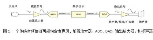
As shown in Fig. 1, the traditional audio signal chain includes a microphone, a preamplifier, an analog-to-digital converter (ADC), a digital to analog converter (DAC), an output amplifier, and a speaker, which are connected by analog signals. However, since the analog circuit is pushed to the edge of the signal chain, more digital interfaces will appear among the integrated circuits in the signal chain. DSP is usually connected digitally. Generally speaking, transducers and amplifiers only have analog interfaces, but now digital interfaces are also included.
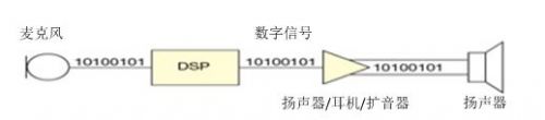
At present, integrated circuit designers are integrating the ADC, DAC and modulator in the transducer into the other end of the signal chain, so that it is not necessary to place any analog audio signal on the printed circuit board (PCB), and the number of devices in the signal chain is reduced. Fig. 2 shows an example of a complete digital audio signal chain.
There are many standards for digital audio data transmission. Many formats can be used to realize inter IC communication on the same PCB, such as I2S (inter IC Audio), TDM (time division multiplexing) and PDM (pulse time division multiplexing) formats. Other audio formats are mainly used for data connection between different printed circuit boards through cables, such as S / PDIF and Ethernet AVB.
This paper focuses on the differences, advantages and disadvantages of digital audio formats between ICs. If audio components with mismatched Digital interfaces are selected, the system design will become more complicated unnecessarily. Understanding the advantages and disadvantages of different interfaces before selecting components will help improve the efficiency of component selection and ensure the most efficient implementation of the signal chain.
Inter IC Audio (12s) is the most common digital audio format used for audio data transmission between integrated circuits. Philips semiconductor (now NXP semiconductor) introduced the 12s standard in 1986. The format was revised in 1996. This interface is widely used in the design of CD player for the first time. Now it can be seen in almost any application involving digital audio data conversion between integrated circuits. Most audio ADCs, DACs, DSPs, sampling rate converters, and some microcontrollers have I2S interfaces.
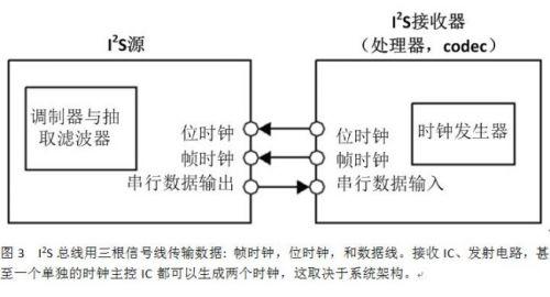
An I2S bus uses three signal lines for data transmission: frame clock, bit clock, and data line. The receiving IC, the transmitting IC, and even a single clock master IC can generate two clocks, depending on the system architecture (Fig. 3). Integrated circuits with I2S ports can usually be set in master mode or slave mode. Unless a sampling rate converter is used in the designed signal chain, the system usually has a single I2S master device to avoid data synchronization problems.
For these signals, the Philips standard names the word selection as WS, the clock as SCK, and the data as SD. However, it seems that circuit manufacturers rarely use these names in their IC data sheets. Word selection is also called lrclk, which means "left / right clock", while SCK is also called BCLK, which means bit clock, or SCLK, that is, serial clock.
The names of IC serial data pins vary from circuit supplier to circuit supplier, and even products of the same supplier have different names. According to a quick survey of the audio IC data table, SD signals can also be called sData, SDIN, sdout, dacdat, adcdat, or other variants of these names, depending on whether the data pin is input or output.
The I2S data stream can carry data of one or two channels at a typical bit clock rate. The typical bit clock rate is between 512 kHz (corresponding to 8 kHz sampling rate) and 12.288 MHz (corresponding to 192 kHz sampling rate). The length of the data word is usually 16, 24, or 32 bits. For the data word length less than 32 bits, the frame length is generally 64 bits, and the unused bits are driven to the low level by the transmitting IC.
Some ICs only support the interface I2S with a maximum 32-bit or 48 bit clock per stereo audio frame, although it is rare. If this type of IC is used, the system designer must ensure that the device connected to the other end also supports these bit clock rates.
Fig. 2 the IC designer is integrating the ADC, DAC and modulator in the transducer into the other end of the signal chain, thus eliminating the need to place analog audio signals on the PCB and reducing the number of devices on the signal chain. The figure shows an example of a complete digital audio signal chain.
Although I2S is the most commonly used format, there are other variants of the same three line structure, such as left aligned, right aligned and PCM mode. These formats differ from I2S in the position of the data word in the frame, the polarity of the clock, or the number of bit clock cycles in each frame.
TDM format
Some ICs support multiple I2S data input or output using a common clock, but this method obviously increases the number of pins required for data transmission. When data of more than two channels are transmitted on the same data line, TDM format shall be used. The TDM data stream can carry up to 16 channels of data and has a data / clock structure similar to I2S.
The data of each channel uses a slot on the data bus, whose width is equivalent to 1 / N of the frame, where n is the number of transmission channels. For practical reasons, n is usually rounded to the nearest power of 2 (2, 4, 8, or 16), and any redundant channels are idle. A TDM frame clock is usually implemented as a pulse of one bit width, which is opposite to the 50% duty cycle clock of I2S. Clock rates above 25 MHz are usually not used for TDM data because higher frequencies can cause board layout problems to be avoided by printed circuit board designers.
TDM is often used in systems where multiple sources feed into one input terminal, or a single source drives multiple devices. In the former case (multiple sources feed into one input), each TDM source shares a common data bus. The source must be configured to drive the bus during its applicable channel, and when other devices are driving other buses, its driver must be set to three states.
There are no other standards similar to Philips I2S for TDM interface. Therefore, many ICs have their own slightly different TDM implementation methods. These changes are reflected in clock polarity, channel configuration, and tristate and drive of idle channels. Of course, in general, different ICs can work together, but the system designer must ensure that the output format of one device meets the expectation of the input end of the other device
PDM data connection
PDM data connection is becoming more and more popular in portable audio applications such as mobile phones and tablets. PDM has obvious advantages in size limited applications, because it can place audio signals around high noise circuits such as LCD screens, without having to deal with the interference problems that analog audio signals may face.
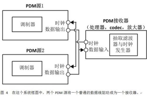
With PDM, only two signal lines can transmit two audio channels. As shown in the system block diagram of Fig. 4, two PDM sources drive a common data line as a receiver. The system master generates a clock that can be used by two slave devices. The two slave devices use the edge of the clock alternately and output their data through a common signal line.
These data are modulated in a 64 × So as to form a clock which is usually 1 to 3.2 MHz. The audio signal bandwidth increases with the increase of the clock frequency. Therefore, a clock with a lower frequency can be used in the system, thereby offsetting the reduced bandwidth for saving power consumption.
The architecture based on PDM is different from I2S and TDM in that the decimation filter is not in the transmitting IC but in the receiving IC. The source output is the original high sampling rate modulated data, such as the output of sigma delta modulator, rather than the decimated data as in I2S. The architecture based on PDM reduces the complexity of the source device and usually uses the decimation filter already existing in the codec ADC.
In this way, the system designer can not only take advantage of the audio codec that may have been used, but also take advantage of the fact that the digital data connection is not sensitive to interference. In addition, a more efficient decimation filter can be realized by using a finer silicon process scale for encoder or processor manufacturing rather than a process for microphone IC.
Codecs, DPS, and amplifiers have had I2S ports for many years, but until now, system input devices such as microphones are still analog or PDM outputs. As the digital interface gets closer to both ends of the signal chain, new ICS will be required to support the new system architecture.
Microphones with integrated I2S interface (such as adm441 MEMS microphone from analog devices) make it easy for designers to use this element in systems where it is not easy to use PDM microphones or systems where analog interfaces are not desired. Only a few audio codecs can accept PDM input, and few processors designed specifically for mobile phones and tablets can natively accept this type of data stream.
In some designs, an I2S output microphone can completely eliminate any analog front-end circuit, so many designs may only have one ADC and PGA, thus supporting a single input of the microphone to the processor. An example of such a system is a wireless microphone with a data transmitter. The wireless transmission SOC may not have a built-in ADC, so a fully digital connection between the transducer and the transmitter can be realized by using an I2S microphone.
I2S, TDM and PDM audio interfaces have their own advantages and the most suitable applications. As more audio ICs switch from analog interface to digital interface, system designers and architects will need to know which interface is most suitable for their specific design. From the microphone to the DSP and then to the amplifier, such a digital signal chain can be completely separated from the PCB and only exists in the audio domain.
|
Disclaimer: This article is transferred from other platforms and does not represent the views and positions of this site. If there is infringement or objection, please contact us to del
中恒科技ChipHomeTek
|

 Service mailbox
 13823783658
 ChatNow