Hot KeyWords:CST8002D  CST6118  CST6508  XS9971   CST118S  CST2466  矽源特科技

Technology Exchange
You are here : Technology Exchange

Five test points to understand the efficiency and performance of motor driver

Views:129Time:2022-10-26
    According to the data of the US Department of energy (DOE), the motor system is critical to the operation of almost all plants, accounting for 60% to 70% of the total power consumption. Doe also identified variable frequency drives (VFDs) as a source of significant cost savings for the plant. Not surprisingly, motor drives are widely used in many industries and facilities. In order to ensure the normal operation time of these motor systems, performing maintenance and troubleshooting becomes the first priority.

Challenges in testing motor drives
    Troubleshooting and testing of motor drives (also known as variable frequency drives (VFD), variable speed drives (VSD), or variable speed drives (ASD)) are usually performed by experts using a variety of test instruments including oscilloscopes, multimeters, or other tools. These tests may involve a certain degree of trial and error using ancient exclusion methods. Due to the complexity of the motor system, the test is usually conducted once a year, unless the system begins to fail. Considering that the equipment usually lacks or has incomplete work history, there may be problems in determining where to start the test. This includes recording specific tests and measurements previously performed, work completed, or the adjusted condition of individual components. Advances in testing technology have removed some challenges. Newer instruments such as fluke motor drive analyzer (mda-510 and mda-550) are designed to make motor drive testing more efficient and insightful, and to record the whole process step by step. These reports can be saved and compared with subsequent test results to provide a more comprehensive understanding of the maintenance history of the motor drive.

Simpler VFD troubleshooting method
    These advanced motor driver Analyzers combine the functions of meters, hand-held oscilloscopes and recorders with the guidance of skilled instructors, and guide you to complete basic tests with screen prompts, clear setting diagrams and step-by-step instructions prepared by motor driver experts. This new method of decomposing and simplifying complex tests enables experienced motor drive experts to work quickly and confidently to obtain the detailed information they need. It also opens a way for inexperienced technicians to start motor driver analysis more quickly.
    By implementing a set of standard tests and measurements at key points in the system, the root cause of motor drive system failure can be found, or routine preventive maintenance inspection can be performed. Starting from the power input end, the key tests are completed in the whole system using different measurement technologies and evaluation standards, and finally at the output end.

The following are the basic tests for troubleshooting motor drives:
    Please note that fluke motor drive analyzer will guide you through these tests and automatically perform many required calculations so that you can be confident in the results. In addition, you can save the data to the report at almost any test point, so that you can upload the document to the computerized maintenance management system (CMMS) or share it with colleagues or consulting experts.
    Safety tips: please read the product safety instructions before starting the test. Do not work alone. Please observe local and national safety regulations. Wear personal protective equipment (approved rubber gloves, protective masks and flame-retardant clothing, etc.) to prevent injury caused by electric shock and arc when dangerous live conductors are exposed.
    To start each test with fluke motor drive analyzer, simply connect the test probe according to the chart and press next.
Step by step measurement connection guidance in driver input test
1. Drive input
    In order to determine whether there is distortion, interference or noise in the feed circuit of the driver that may affect the grounding of the power supply, the power supply of the motor driver should be analyzed first.
test
    Comparing the nominal rated voltage of the driver with the actual supply voltage can quickly check whether the value is within the acceptable limit. Exceeding this range by more than 10% indicates that there is a problem with the power supply voltage. Determine whether the input current is within the maximum rated range and whether the wire size is appropriate.
    ·Compare the measured frequency with the specified frequency. A frequency difference of more than 0.5 Hz may cause problems.
    ·Check whether the harmonic distortion is within the acceptable range. Visually check the waveform shape, or view the harmonic spectrum screen that displays both total harmonic distortion and individual harmonics. For example, the flat top waveform may indicate a nonlinear load connected to the same feed circuit. If the total harmonic distortion (THD) exceeds 6%, there may be a problem.
    ·Check the voltage imbalance on the input terminals to ensure that the phase imbalance is not too high (less than 6% - 8%) and that the phase rotation is correct. A high voltage unbalance reading indicates a phase break. Reading above 2% may cause a voltage gap and cause the driver overload fault protection device to trip or interfere with other equipment.
    ·Current unbalance test. Excessive imbalance may indicate a problem with the drive rectifier. A current imbalance reading of more than 6% may indicate a problem with the inverter of the motor drive and may cause problems.
2. DC bus
    AC to DC conversion within the drive is critical. In order to obtain the best performance of the driver, it is necessary to ensure that the voltage is correct, fully filtered and low ripple level is maintained. High ripple voltage may indicate that the capacitor is faulty or the connected motor is of incorrect specification. The recording function of fluke mda-500 series motor drive analyzer can dynamically check the performance of the DC bus under the working mode under load. You can also use fluke Scopemeter ® Test tool or advanced multimeter.
Ripple on DC bus
    ·It is determined whether the DC bus voltage is proportional to the peak value of the input line voltage. In addition to the controllable rectifier, the voltage should be approximately 1.31 to 1.41 times the RMS line voltage. A low DC voltage reading will trip the driver, which may be caused by low input supply voltage or distortion of input voltage (such as flat top).
    ·Check the line voltage peak amplitude for any distortion or error. This may cause overvoltage or undervoltage errors. A difference of + / - 10% between the DC voltage reading and the nominal voltage may indicate a problem.
    ·It is determined whether the peaks of the AC ripple have different repetition levels. After AC-DC conversion, a small AC ripple component will remain on the DC bus. Ripple voltages in excess of 40 V may be caused by capacitor failure or driver ratings that are too small for the connected motor or load.
Voltage and current at driver output
3. Driver output
    Testing the driver output is critical to the normal operation of the motor and can provide clues to problems in the driver circuit.
test
    ·Determine whether the voltage and current are within the limits. A high output current may heat the current, thereby reducing the insulation life of the stator.
    ·Check the voltage / frequency ratio (V / Hz) to ensure that it is within the specified limits of the motor. High ratio may overheat the motor; A low ratio will cause the motor to lose torque. Stable frequency and unstable voltage may indicate DC bus problems; Unstable frequencies and stable voltages may indicate switching (IGBT) problems. Unstable frequency and voltage indicate a possible problem with the speed control circuit.
    ·When checking the driver output, the emphasis is on measuring the voltage frequency ratio (V / F) and voltage modulation. When the measured value of V / F ratio is high, the motor may overheat. When the V / F ratio is low, the connected motor may not be able to provide the required torque on the load, resulting in insufficient execution of the expected process.
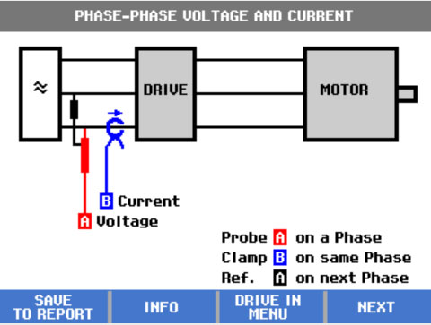
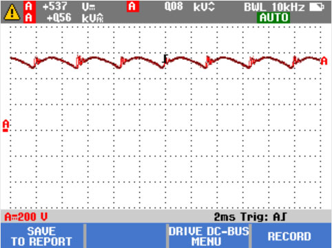
    ·Check voltage modulation using phase to phase measurement. High voltage peaks may damage the motor winding insulation and cause the driver to trip. A voltage peak exceeding 50% of the nominal voltage may cause problems.
    ·Check the steepness of the switching pulse indicated by the driver reading. The rise time or steepness of the pulse is expressed by the DV / dt reading (the rate of change of voltage over time), which shall be compared with the specified insulation value of the motor.
    ·Test the switching frequency of phase to DC. Identify whether there is a potential problem with the electronic switch or the grounding, which may indicate a problem when the signal floats up and down.
    ·The measurement of voltage imbalance is preferably carried out under full load conditions. Voltage unbalance shall not exceed 2%. The voltage imbalance will cause the current imbalance, which will cause the motor winding to overheat. The cause of the imbalance may include a driver circuit failure. If one phase fails, it is called "single-phase operation", which may cause the motor to heat up, fail to start after shutdown, greatly reduce the efficiency, and may damage the motor and the connected load.
    ·Measure the current unbalance. For three-phase motor, the current unbalance shall not exceed 10%. A large imbalance when the voltage is low may indicate that the motor winding is short circuited or the phase is short circuited to ground. A large imbalance may also cause the driver to trip, the motor temperature to be too high and the winding to be burnt
4. Motor input
    It is very important to supply voltage to the input terminals of the motor, and it is also important to select the wiring between the driver and the motor. Incorrect wiring selection can cause damage to the driver and motor due to high voltage peaks. These tests are basically the same as the driver output tests described above.
test
    ·Check whether the current on the terminal is within the rated value of the motor. Too high a current will cause the motor to overheat and shorten the life of the stator insulation, leading to premature motor failure.
    ·Voltage modulation helps to identify high voltage peaks to ground that may damage the motor insulation.
    ·Voltage imbalance will seriously affect the service life of the motor and may be a symptom of inverter failure. This may cause a voltage gap and cause the overload fault protection device to trip.
    ·Current imbalances may indicate voltage imbalances or driver rectifier problems.
5. Motor shaft voltage
    Voltage pulses from the motor driver will couple between the motor stator and the rotor, resulting in voltage on the rotor shaft. When the voltage of the rotor shaft exceeds the insulation voltage of the bearing grease, flashover current (spark) may occur, resulting in pitting and groove corrosion of the motor bearing race. This damage may lead to premature failure of the motor.
test
    Measure the voltage between the motor frame and the drive shaft. For example, mda-550 provides a carbon fiber brush probe for this purpose. This test can easily detect the presence of destructive flashover currents, while pulse amplitude measurement and event counting functions allow you to take action before a fault occurs.

    Disclaimer: This article is transferred from other platforms and does not represent the views and positions of this site. If there is infringement or objection, please contact us to del
   
 中恒科技ChipHomeTek

Back Top