Open-loop closed-loop Class D amplifier has gradually become the preferred choice of consumer audio electronics designers. To accurately grasp the performance of the amplifier, different ways are needed to check the effect of power ripple. Today‘s audio designers attach great importance to reducing system costs, reducing volume and improving sound quality, which all require a high power supply noise suppression architecture to achieve. However, the power supply rejection ratio (PSRR) measurement cannot accurately determine the performance of Class D bridged load (BTL) amplifiers. This paper will discuss the traditional PSRR specification and measurement technology, and explain why it can not accurately measure the power supply suppression function of the amplifier. In addition, this paper will provide another way to inspect the power ripple effect in the audio performance of the amplifier.
Body:
For a long time, the power supply rejection ratio (PSRR) has been the best way to evaluate whether the amplifier can suppress the power supply noise at the output end. However, with the popularity and performance advantages of Class D amplifier, it is insufficient to rely solely on PSRR as an indicator of power supply noise suppression. This is particularly evident when comparing the PSRR specifications of the open-loop closed-loop digital input I2S amplifier. PSRR specifications are mostly the same. However, when listening to the sound quality of the amplifier supplied by a non-ideal power supply, the difference in sound quality can be clearly identified. This paper will outline the traditional PSRR measurement method, and explain why this measurement method cannot accurately determine the power supply suppression performance of Class D amplifier in the bridged load (BTL) configuration, and provide an alternative method that can effectively measure the power supply noise effect in Class D amplifier.
To understand why PSRR measurement can no longer accurately determine the power supply suppression performance, we must first review the history of class AB amplifier leading consumer audio electronics. Class AB amplifier used to be configured with single-ended (SE) or BTL output, which is the same as the current configuration. In fact, SE AB amplifier generally uses split rail supply (i.e.+/- 12V), because the power supply mainly uses the transformer type, and adding a second rail will not cause cost burden. BTL configuration is more commonly used for audio system of non-split rail power supply. However, regardless of SE or BT configuration, class AB amplifier can achieve good PSRR through the basic structure of class AB amplifier and the output voltage lower than the power rail voltage.
For class AB amplifier, PSRR measurement can accurately indicate the ability of the amplifier to suppress power noise, especially for SE configuration (see below). First, let‘s understand the impact of Class D amplifier on the market. The efficient operation of Class D amplifier has changed the ecology of the market, resulting in a large number of innovations in industrial design, especially the reduction of size. However, the architecture of this type of amplifier is fundamentally different from that of AB type amplifier, and BTL is almost uniformly selected as its output configuration.
In BTL configuration, the Class D amplifier has two output stages (also known as full-bridge type) composed of four FETS. SE Class D amplifier has only a single output stage (also known as half-bridge type) composed of two FETS. Compared with the SE configuration, the BTL output configuration has many advantages, including four times the output power of a specific power rail, better bass response, and excellent switching noise suppression performance. The disadvantage of BTL architecture is that it requires twice the number of FET transistors, which means that the size of the crystal and the related costs increase, and the cost of reconstruction filter (LC filter) doubles. In the current market where SE and BTL Class D amplifiers are parallel, BTL accounts for the vast majority.
In Class D BTL configurations, the traditional PSRR measurement cannot work. In order to understand the reasons, we must first understand the operation mode of Class D amplifier and the measurement mode of PSRR. Class D amplifier is a switching amplifier. The output will switch between rails at a very high frequency, which is generally above 250kHz. The audio will be used for pulse width modulation (PWM) of switching frequency (square wave), and then the reconstruction filter (LC filter) will be used to capture the audio in the carrier frequency. The performance of this switching architecture is quite high (the architecture is the same as the switching mode power supply), but its sensitivity to power supply noise is also much higher than that of the traditional class AB amplifier. Think again, the output of the amplifier is basically the power rail (after pulse width modulation), so any power supply noise will be directly transmitted to the output of the amplifier.
Power supply rejection ratio (PSRR) is a measurement method to determine the extent to which the amplifier suppresses power supply noise (i.e. ripple). This is an important parameter that must be considered when selecting audio amplifier, because audio amplifier with poor PSRR usually requires high cost power supply and/or large decoupling capacitance. In the consumer market, the cost, size and weight of the power supply are important design considerations, especially when the size and shape of the power supply are shrinking, the price is falling rapidly, and the portable design is becoming increasingly popular.
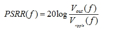
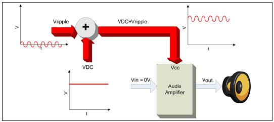
In the traditional PSRR measurement, the power supply voltage of the amplifier includes DC voltage and AC ripple signal (VRipple). The audio output is AC grounded, so there will be no audio during the measurement. Since all the decoupling capacitors of the power supply voltage have been removed, the Vripple will not be significantly weakened (Fig. 1). The output signal is then measured and the PSRR is calculated using Equation 1:
Figure 1: Traditional PSRR measurement
Figure 2 shows the traditional PSRR measurement on a Class D BTL audio amplifier. The output before and after the reconstruction filter obviously has power supply noise. However, please note that the noise is in phase in the load. Therefore, when measuring PSRR, Vout+and Vout - ripple will cancel each other and produce an error indication of power supply suppression. However, it can be clearly seen that the amplifier is transmitting power supply noise directly to the output. This type of PSRR measurement cannot indicate the extent to which the amplifier suppresses the power supply noise, and the main reason why the PSRR measurement cannot work is that the input is AC grounded during the measurement. In practical applications, the function of the amplifier is to play music, which is the part that must be considered.
When playing audio, the power supply noise will be mixed/modulated with the incoming audio, and the whole audio frequency band will produce different degrees of distortion. The offset effect of BTL configuration itself can no longer eliminate the noise, which is called intermodulation distortion (IMD) in the industry. IMD is the result of mixing two or more signals with different frequencies. In general, the signal frequency formed will not be the harmonic frequency (integer multiple) of one of the signals.
Figure 2: BTL Class D PSRR measurement with LC filter
Before continuing to discuss how to deal with the defects of PSRR measurement, let‘s talk about feedback first. From the previous discussion, it should not be difficult to detect that Class D amplifier itself has power noise problems. If it does not provide feedback, this will become a major defect (in higher-order audio applications, open-loop amplifiers can achieve good sound quality, but such amplifiers generally have relatively stable and high-performance power supply, and the cost is also quite high, so it cannot be compared.) To strengthen the sensitivity to power noise, Designers can design a system with well regulated power supply, but the cost will increase, or use Class D amplifier with feedback (also known as closed loop amplifier).
In today‘s consumer electronics market, most analog input Class D amplifiers use closed circuits. However, the digital input I2S amplifier has its defects. The I2S amplifier is directly connected to the audio processor or audio source through the digital bus. Because it avoids unnecessary digital to analog conversion, it can reduce costs and improve performance. However, the closed loop I2S amplifier is not common in the market today, because it is always very difficult to establish a feedback loop to sample PWM output and add it to the internal I2S digital audio stream. In the analog feedback system, it is usually the sum of analog output and analog input, so it is relatively simple and feasible. However, with the evolution of the I2S market, most of the I2S amplifiers adopt the approach of analog input amplifiers and adopt feedback architecture.
Obviously, PSRR is not an effective method to measure the power supply suppression of BTL Class D amplifier, so what should be done? Now let‘s turn back to the term intermodulation. The designer needs to measure the intermodulation distortion produced when playing audio and its corresponding THD+N configuration. Before we begin, let‘s review the SE architecture. In the SE architecture, no matter Class AB, Class D or Class Z, there is no offset effect of BTL architecture, because one end of the speaker is connected to an amplifier and the other end is grounded. Therefore, for Class AB or Class D amplifiers, in the SE architecture, the traditional PSRR measurement can accurately indicate the power supply noise suppression situation.
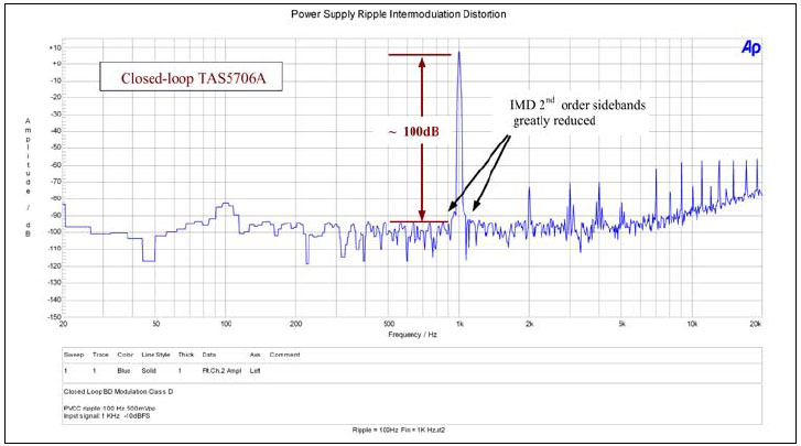
After the experiment, some data can be obtained, and the data obtained from the following series of measurements can be used to analyze and compare the power ripple IMD of open loop and closed loop I2S amplifiers. The digital 1kHz tone is injected into the input of the amplifier, while the 100Hz 500mVpp ripple signal is injected into the power supply. The differential output FFT can be obtained through the function of audio accuracy built in FFT, and then the IMD can be observed.
Figure 3 shows the IMD measurement of the closed loop I2S amplifier. Pay attention to the 1 kHz input signal and the almost non-existent side band. The feedback loop is effectively suppressing intermodulation distortion.
Figure 3: TAS5706 closed loop intermodulation curve
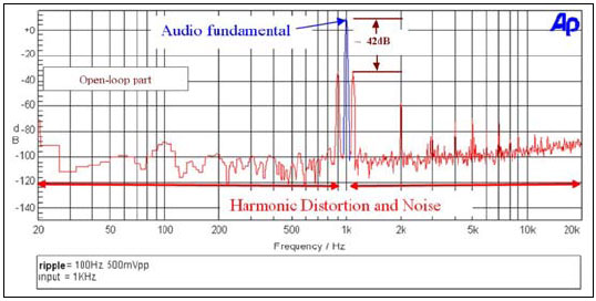
Figure 4 shows the same IMD measurement, but this time it is measured at the I2S open-loop amplifier. The sideband of 900 Hz and 1.1 kHz is quite obvious because it does not suppress the feedback of IMD.
Figure 4: Open circuit intermodulation curve
Here is a good news. In Figure 3 and Figure 4, the effect of power noise IMD can be clearly seen. However, in terms of sound quality, IMD is difficult to achieve qualitative measurement. In this experiment, you can choose to measure THD+N configuration, and the following two measurements will be carried out accordingly. THD+N is measured with 1kHz digital audio and 500mVpp power ripple, and the power ripple frequency is between 50Hz and 1kHz.
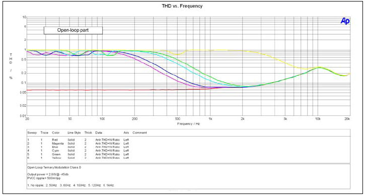
Figure 5 shows the THD+N curve of the open-loop amplifier at different power ripple frequencies. The red line indicates the amplifier performance without any ripple in the power supply, which is the most ideal state. The other curve represents the ripple frequency between 50 Hz and 1 kHz. When the ripple frequency increases, the influence of distortion on frequency bandwidth will also increase. Good open-loop performance can be achieved through well-regulated power supply, but this will increase the cost, which will be a big problem for today‘s highly competitive consumer electronics market.
Figure 5: Open circuit: THD+N and frequency of different PVCC ripple frequencies
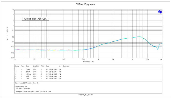
Figure 6 shows the same THD+N curve of the closed loop amplifier. The feedback suppresses intermodulation distortion, so there is no ripple noise in the audio.
Figure 6: Closed circuit: THD+N and frequency of different PVCC ripple frequencies
conclusion
This paper reviews the traditional methods of measuring PSRR, and points out the reason why it can not effectively measure the ripple effect of BTL class D amplifier power supply. The offset effect of the BTL output configuration itself and the absence of any audio during the measurement result in incorrect readings. This is a major defect in specifications, because the power supply noise suppression performance is one of the most important indicators when selecting Class D amplifier, especially when examining the performance difference between digital input (I2S) closed circuit and open circuit amplifier. In order to understand the power supply noise suppression more correctly, it is necessary to check the IMD and THD+N conditions when the output is 1kHz audio signal and the power supply is noisy. At the end of this paper, we explain why the closed loop class D amplifier can compensate for the power supply noise while the open loop amplifier cannot. In the highly competitive consumer electronics market, cost is the core factor to be considered, and whether the closed loop architecture can reduce the system cost is a very important design focus.
|
Disclaimer: This article is transferred from other platforms and does not represent the views and positions of this site. If there is any infringement or objection, please contact us to delete it. thank you!
中恒科技ChipHomeTek
|


 Service mailbox
 13823783658
 ChatNow