Stepper motors are usually used for positioning because they are cost-effective, easy to drive and can be used in open-loop systems - which means they do not need position feedback like servo motors. Stepping motors are used for small industrial machines, such as laser engraving machines, 3D printers, laser printers and other office equipment.
There are many options for stepper motors. For industrial applications, two-phase hybrid stepping motors with 200 steps per revolution are very common. For these motors, "mixing" refers to how they use permanent magnets and toothed iron rotors (for example, variable reluctance motors), and "200 steps" refers to the motor moving 1.8 ° between each step. These steps are a function of the number of teeth on the rotor and stator.
This paper will focus on two-phase hybrid stepping motors, because they are common.
How micro steps work
The stepper motor can be moved less than the whole step. This process is called microstepping and is realized by modulating the current through the winding, so that the rotor can be positioned between the whole steps. The designer can specify almost any size for the microstep, because the step size is only limited by the resolution of the digital-to-analog converter (DAC) and amplifier that drive the winding current. 1/256 or even 1/1024 resolution is not uncommon.
In fact, for most mechanical systems, such fine micro-stepping does not always improve the positioning accuracy. Many other factors have a negative impact on performance.
There are several angular errors in microsteps. One is the defect of the motor itself - mechanical and magnetic - because the motor has no perfect sine current to position transfer function. Even if you apply perfect sine and cosine current to the motor, the motion is not perfect linear.
Another error is the current regulation accuracy of the stepping motor controller. The typical step IC is about 5% of the full scale current. In addition, the current regulation match between the two channels may not be perfect. These inaccurate results reduce the positioning accuracy.
Step motor torque
Rated holding torque of stepping motor. Holding torque is the torque required to pull the motor away from the full step position, and also the torque that can be generated when the motor moves the full step. After each complete step, the teeth align with the magnetic circuit of the, thus producing a strong torque.
During microstep, the holding torque will be reduced because the rotor is kept between the full step position and the magnetic circuit is longer. This incremental holding torque can be calculated by formula (1):
Incremental holding torque=(full step holding torque) x sin (90 °/X) (1)
Where X is the number of microsteps
For example, for 1/8 step, the incremental torque is about 20% of the full step torque. For 1/32 step, the incremental torque is only 5% of the full step torque.
What does this mean for the motion control system? This means that the torque load on the motor must be a small part of the rated holding torque of the motor in order to actually reach the expected position when performing microsteps.
Laboratory measurement
In order to test the position accuracy of micro-stepping, several experiments were carried out. The laboratory is equipped with surface reflectors and lasers mounted on the stepper motor shaft. The beam is reflected from the mirror to the other end of the laboratory at a distance of about 9 m. Then measure the elevation of the laser beam and calculate the angle. Accuracy measurement is mainly limited by the accuracy of beam height measurement; At ± 1mm, this corresponds to an accuracy of ± 0.006 °.
The motor used for the experiment is a typical hybrid motor, usually used for 3D printers and other products. This is a 1.8 ° bipolar motor with a rated current of 2.8A and a holding torque of 1.26Nm.
The accuracy of the motor was measured separately in three experiments. It uses a DC current source to drive two phases, and no torque load is applied to the motor shaft. Instead, only the mirror is on the axis.
The result of this setting shows small nonlinearity, but in general, the angle accuracy is very good; It is about ± 0.03 °, and the motion is monotonous (Fig. 3). In other words, the motor never moves or cannot move in the wrong direction. These errors represent the inherent error of the motor itself, plus the measurement error. Note that 1/32 step corresponds to 0.056 °.
Fig. 3 1/32 step no-load accuracy ensures monotonic motion. Data: Single-chip power supply system
Next, the motor is coupled to a magnetic particle brake, which applies a frictional torque load to the motor.
Repeat the same measurement using a DC current source and apply a torque of approximately 0.1 Nm to the motor shaft. Figure 5 shows that these results are significantly different because there is no movement at every step.
Figure 5 shows significantly different results by increasing the torque by 1/32 step. Data: Single-chip power supply system
This behavior corresponds to the incremental torque calculated for the motor. The incremental torque of 1/32 microstep is about 5% of the holding torque. In this case, the holding torque is 1.26 Nm, and the expected torque generated by one microstep is about 0.06 Nm. However, this is not enough to overcome the friction load, so two microsteps are required before the torque is high enough to overcome the load.
If we increase the torque to 0.9 Nm (about 70% of the stall torque), we need more microsteps to increase the torque to the point where the motor moves (Figure 6).
Figure 6 1/32 step with 0.9 Nm torque requires more microsteps to move the motor. Data: Single-chip power supply system
Two similar experiments were carried out using MPS‘s MP6500 stepper motor driver IC. The PWM current regulation used by the MP6500 driver IC can run from full step to 1/8 step. Figure 7 shows the block diagram of the MP6500.
Figure 7 The MP6500 stepper motor driver adopts PWM based current regulation. Data: Single-chip power supply system
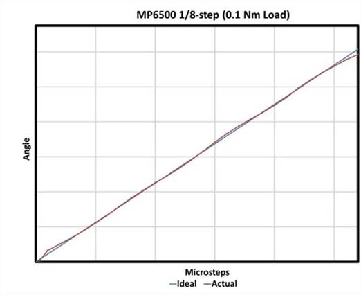
In order to test whether the precision of the traditional stepper motor driver IC is different from that of the DC current source, the tests were carried out in 0.1 Nm torque and 1/8 step mode. The torque generated by 1/8 step is about 20% of the whole step, that is, 0.25 Nm, which is greater than the applied torque of 0.1 Nm. Figure 8 shows the results, indicating that the actual angle tracks the ideal angle.
Figure 8 In this test, the MP6500 stepper motor driver IC uses 1/8 step length and 0.1 Nm torque. Data: Single-chip power supply system
For the second test, a torque of 0.4 Nm was applied. This is greater than 1/8 step incremental holding torque (0.25 Nm). As expected, the micro step is skipped (Figure 9).
Figure 9 In the second test, the MP6500 uses 1/8 step and 0.4 Nm torque. Data: Single-chip power supply system
Mechanical considerations
In order to obtain the required precision in micro-stepping, designers must pay close attention to the mechanical system.
There are several ways to generate linear motion using a stepping motor. One method is to connect the motor to the moving parts using a belt and pulley. In this case, the rotation is converted to linear motion. The moving distance is a function of the motor movement angle and the pulley diameter.
The second method is to use the lead screw or ball screw. The stepping motor is directly connected to the end of the screw, so when the screw rotates, the nut moves in a linear manner.
In both cases, whether linear motion actually exists as a result of a single microstep depends on the friction torque. This means that in order to obtain accuracy, the friction torque must be reduced.
For example, many guide screws and ball screw nuts have certain preload adjustability. Preload is a force used to prevent recoil, which will produce some gaps in the system. However, increasing the preload will reduce the back clearance, but also increase the friction. Therefore, there is a trade-off between rebound and friction.
|
Disclaimer: This article is transferred from other platforms and does not represent the views and positions of this site. If there is any infringement or objection, please contact us to delete it. thank you!
中恒科技ChipHomeTek
|


 Service mailbox
 13823783658
 ChatNow